

How do you connect RS232 to BS2
 Dr.Zaius
Posts: 16
Dr.Zaius
Posts: 16
Hi BS2 gurus
.I want to connect the Basic Stamp2 to an RS232 cable. I know that USB is more convenient, but I need to understand this interface for future references. Im sure some fellow BS2 users might be interested on this for their own projects.
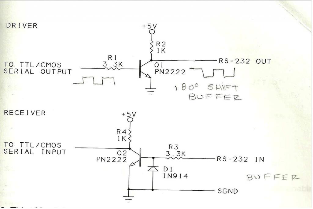
Im not too sure about RS232, on the circuit level; its been a while since Ive done electronics. As I understand the BS2 uses a Half Duplex circuit to send data and receive data as the schematic shows

Im not to sure how the Diode works on the lower circuit, I guess its the same as the top but in reverse.
I want to use a Max232 chip see schematic
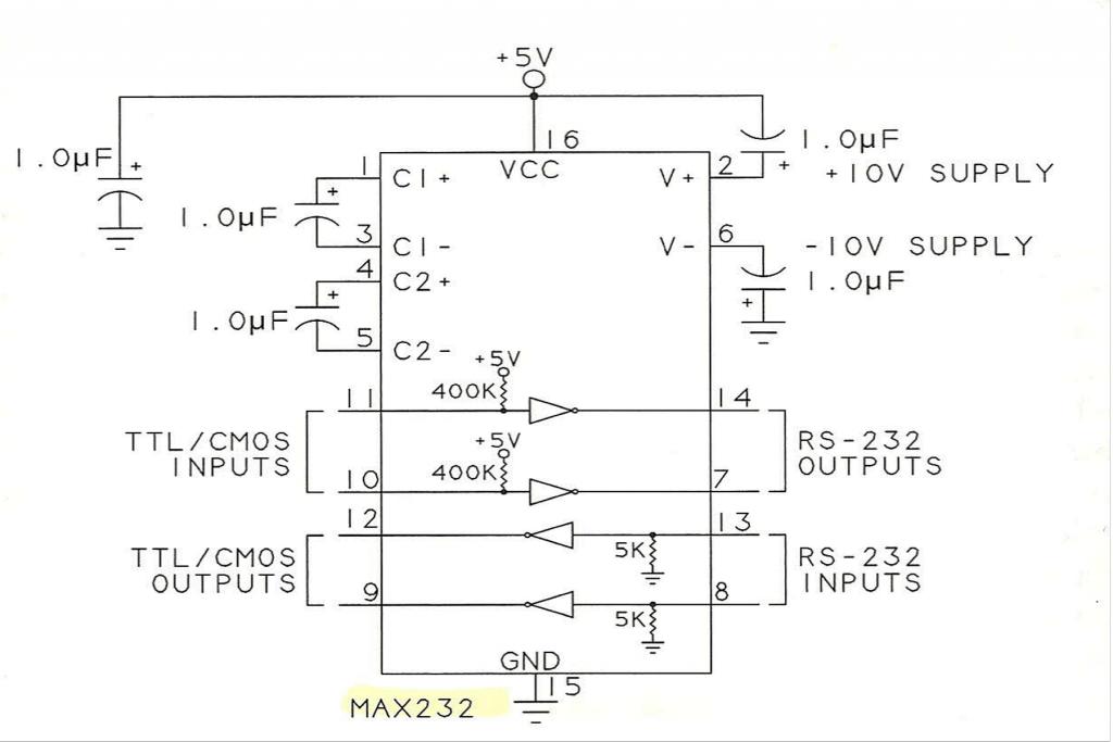
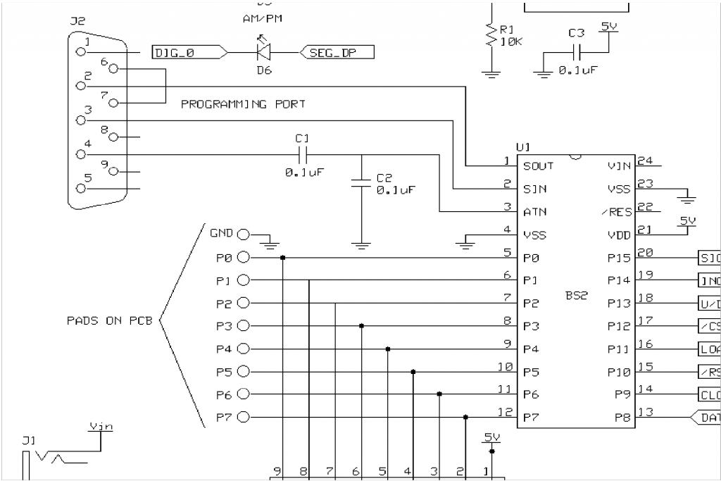
So on the BS2 Pin 1 goes to Pin 10 on Max Pin 7 then goes to Pin 2 on RS232 Cable, Pin 3 on RS232 to Pin 13 on Max Pin 12 to Pin 2 on BS2 right? Then I ask myself isnt there a Clock somewhere .Im not too sure As I was looking for Info I found a neat project In Nuts and Volts using a BS2 as a Clock with the BS2 code, its was interesting to me how the author connected the BS2, see schematic.

On the RS232 Pin 2 is RX, Pin3 Tx, Pin4 DTR; Clock right?, Pin6 DSR; to Pin7 RTS these two connected makes an echo right?
I wanted to use the Max 232 chip, because it has more control for the data, but Im kinda lost there, the last schematic looks easier to connect ..Any Ideas will help. Thanks.
Im not too sure about RS232, on the circuit level; its been a while since Ive done electronics. As I understand the BS2 uses a Half Duplex circuit to send data and receive data as the schematic shows
Im not to sure how the Diode works on the lower circuit, I guess its the same as the top but in reverse.
I want to use a Max232 chip see schematic
So on the BS2 Pin 1 goes to Pin 10 on Max Pin 7 then goes to Pin 2 on RS232 Cable, Pin 3 on RS232 to Pin 13 on Max Pin 12 to Pin 2 on BS2 right? Then I ask myself isnt there a Clock somewhere .Im not too sure As I was looking for Info I found a neat project In Nuts and Volts using a BS2 as a Clock with the BS2 code, its was interesting to me how the author connected the BS2, see schematic.
On the RS232 Pin 2 is RX, Pin3 Tx, Pin4 DTR; Clock right?, Pin6 DSR; to Pin7 RTS these two connected makes an echo right?
I wanted to use the Max 232 chip, because it has more control for the data, but Im kinda lost there, the last schematic looks easier to connect ..Any Ideas will help. Thanks.
1024 x 683 - 47K

1024 x 683 - 54K
1024 x 683 - 73K
Comments
I would suggest you first look at the Help files in the programming software under SERIN and SEROUT. There are numerous examples and explanation.
To interface "real" RS-232 signals (as opposed to TTL level ), the Stamp can receive those signals as long as a resistor (10K-47K) is used in series with the Stamp input to drop the voltage to a safe level. As far as talking, most rs-232 devices will accept the 5 volts generated by the Stamp as a valid signal. You will have to use the "inverted" option.
As you've noted, there are level shifting chips which may be of value in some applications. The MAX233 is my favorite because it dosen't need external capacitors and the ST232ABN is a lower cost alternative to MAX232.
Cheers,
Basic Stamp functions SERIN/SEROUT do not interact with RS232 protocol in such interfacing function - they only transfer selected data in and out of Basic Stamp - as mentioned - there is no buffer in these functions. Such buffering / control would be proviided by the RS232 interface.
To gain better understanding of function of RS232 protocol as interface standard I wouod suggest you study Parallax document "BASIC Stamp Programming Protocol" . It covers how partial RS232 protocol is used in programming the BS.
I am assuming you are interested in the entire communication channel and not necessary limited to PC interface.
However , keep in mind that PC COM port is often emulated by USB interface. The RS232 protocol would still be used , but
in cojunction with USB. It still works the same but with added USB hardware.
In either case - be mindful of proper terminology - "loopback" in RS232 and "loopback" in Parallax editor are not the same.
As far as "missing clock" - an asynchronous serial communication channel does not need it - the synchronization is achieved by start/ stop bits in the data itself. Such clock would be evident in synchronus communication channel only.
Cheers Vaclav
.
Here's how my journey went;
1) Article in download section here covered what I needed (RS232 and VB);
http://www.parallax.com/Resources/NutsVoltsColumns/NutsVoltsVolume3/tabid/445/Default.aspx
It took less than 2 days based on this information!
2) Initially, I used portA pins 0 and 1 instead of the built in serial pins. This required a level shifter or MAX232 type device. If you google "rs232 pic" the 7th or so listing is a level shifter circuit I used ;
http://picprojects.org.uk/projects/simpleSIO/ssio.htm
This worked well, and I captured screenshots of the levels and timing, but ended up not using this to save board space and simpify. You can use the BS serial pins (the ones used for programming) and then you don't need the level shifter, but they WILL echo RX data.
3) Connect to hyperterminal to verify your BS code!