

How do I sense the state of the gate of this SCR on a prop pin
 bongk
Posts: 14
bongk
Posts: 14
Hi all,
Getting stuck on a pinball project that I'm trying to get done for the Midwest Gaming Conference next weekend.
I'm removing some indicator bulbs and reading their state on the prop instead.
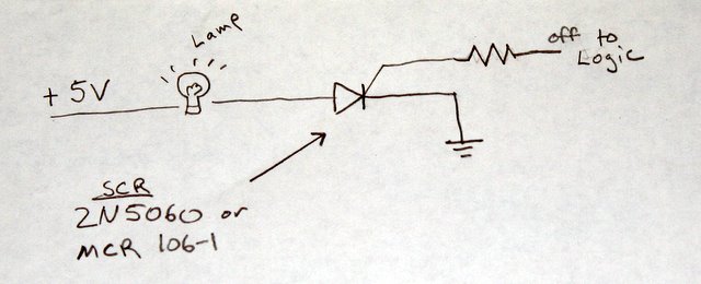
The original circuit is attached. I want to remove some lamps and sense whether the bulbs would be on by connecting to the wires that were cut. The bulbs all share a common +6.3V feed, each is turned on and off by an SCR/Reverse Blocking Thyristor that "opens" its connection to ground.
I had assumed bulb-off would be high-impedance and bulb-on would be open to ground, but it seems like I actually need to have a resistive load (like the bulb) to get a measurable change in the voltage. I attached a sketch of my circuit that doesn't work. Is there a way to do what I'm trying without adding a bulb or other hot load back to the circuit?
Thanks!
Kevin
Getting stuck on a pinball project that I'm trying to get done for the Midwest Gaming Conference next weekend.
I'm removing some indicator bulbs and reading their state on the prop instead.
The original circuit is attached. I want to remove some lamps and sense whether the bulbs would be on by connecting to the wires that were cut. The bulbs all share a common +6.3V feed, each is turned on and off by an SCR/Reverse Blocking Thyristor that "opens" its connection to ground.
I had assumed bulb-off would be high-impedance and bulb-on would be open to ground, but it seems like I actually need to have a resistive load (like the bulb) to get a measurable change in the voltage. I attached a sketch of my circuit that doesn't work. Is there a way to do what I'm trying without adding a bulb or other hot load back to the circuit?
Thanks!
Kevin
640 x 260 - 37K

640 x 437 - 87K
Comments
-Phil
Found some documentation on the board. Yes, it appears the bulbs are driven by a DC current that hasn't been cleaned up, it still has the zero crossings. The SCR is strobed on the gate to turn the bulb on, and it stays on until the next zero crossing, then it is strobed again...
I want to avoid trying to monitor the gate voltage- I'd have to modify the stock bally lamp board to do that, and more so I think I'd struggle to catch the strobe signals.
Now that I undertstand a little better, could my circuit work if I were to pulse the 3V input signal? (turn on the input signal, wait long enough for a strobe, measure the state (high or low) on the SCR side of the resistor) I'm actually thinking I'd need to step up to a 5V signal and use a smaller resistor so more current flows to the SCR.
Any help is really really appreciated.
Kevin