

Propeller Proto Board wiring question
 SSteve
Posts: 808
SSteve
Posts: 808
Am I correct in interpreting the PPB schematic that the holes I've circled are connected through 10k resistors to 3.3V? (My hardware skills are effectively non-existent.)
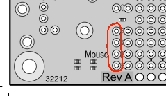

239 x 139 - 27K
Comments
So I guess to answer your question, yes, one of those holes is pulled-up to 3.3V through 10K. I don't have a Proto Board in front of me to verify that it is the left-most hole that is pulled-up, but you should be able to trace it out on the board or with a voltmeter. The other side of the pair will connect back to pins P24-P27 on the propeller.