Shop OBEX P1 Docs P2 Docs Learn Events
Arduino Adapter for Gadget Gangster's Propeller Platform. — Parallax Forums

Arduino Adapter for Gadget Gangster's Propeller Platform.

Martin HodgeMartin Hodge Posts: 1,246
edited 2011-12-31 05:41 in Propeller 1
Preliminary design, ready for first prototype. It's a very simple board that provides the 6-ch ADC and current limiting resistors. Bare solder jumpers are on the back to easily bypass any of the CL resistors should one need to interface with 3.3v shields such as the ETHShield.
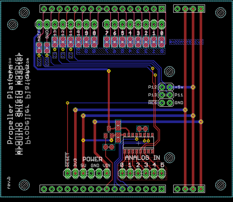
PPASA.png

Schematic: ArPlat-b.pdf
802 x 696 - 58K

Comments

  • Oldbitcollector (Jeff)Oldbitcollector (Jeff) Posts: 8,091
    edited 2011-03-08 09:00
    That's really slick! Provides an excellent way to cross to Propeller without shelfing current boards.

    OBC
  • schillschill Posts: 741
    edited 2011-03-09 05:38
    Funny, but to me the boards look like they are oriented "backwards" relative to each other. I always picture the platform and the Arduino boards with the power connections to the left.

    Not a criticism but something to remember is that the analog inputs on an Arduino board are not limited to being analog. They can be used as generic digital I/O as well. Most people who design things to interface with Arduino shields seem to think that users always require these to be analog.

    It might be useful to connect the Arduino analog pins (CH0-CH5) to some of the other platform pins in addition to the A/D converter. This way you could use them for digital I/O (especially the O part) as well. Jumpers could be used to select whether they are connected to the A/D converter or directly to pins.

    Anyway, the board looks really nice and if you go into production with them I'm definitely interested. They're a lot cleaner than my hacked-together adapter "board" (but my board is taller :) ).
  • Nick McClickNick McClick Posts: 1,003
    edited 2011-03-09 10:03
    I think it looks very nice, few thoughts / suggestions;
    • Keep in mind that on the Propeller Platform USB, P0..P3 has an SD card connected to it. If the SD card isn't inserted, each pin has a 10k 3.3v pullup.
    • Here are the dimensions for mounting holes. Looks like 2 of them are already correct, and the other 2 interfere with the Arduino holes, so it probably doesn't matter. For me, the pin header / socket friction is plenty, just as long as there are mounting holes on the base.
    • I like to put some usage info on the board, if possible. Maybe a URL or just the pin mapping info (P0 = In0, etc).
    That's all I can think of!
  • Martin HodgeMartin Hodge Posts: 1,246
    edited 2011-03-09 18:38
    @Schill, yes the boards are back-to-back. With the boards facing the same direction the routing is a horrendous mess with most of the connections traveling all the way across the board. If it's a really big issue to have both powers on the left I can start over though. I already have Propeller P14 and P15 connected to Arduino "Analog In" pins 4 & 5 to provide I2C. With P14 & P15 set as inputs they shouldn't interfere with analog. I could extend that arrangement to all the analog pins pretty easily. I don't see a need for jumpers though as there aren't any other pins to connect them to. (Remember, we're trying to squeeze the Propeller's giant size 13 foot into the Arduino's dinky size 9 shoe!) Unless you're going to Dagwood together PP expansion board(s) with Arduino shield(s), then it could be an issue.

    @Nick. Your comments are duly noted. I think the mounting hole layout is okay, but I'll double check.
  • schillschill Posts: 741
    edited 2011-03-10 05:22
    The board orientations relative to each other are not a problem at all. It just looks odd to me :) . Without knowing ahead of time which Arduino shield might be attached, you will never know which orientation is "best" anyway.

    After looking at the picture again, there are a couple traces I'd consider moving to the other side of the board but this would only be to reduce the number of vias. For example, the Vin trace between the Platform headers could be moved from the red to the blue layer. The red -reset and 3v3 traces for the Arduino header could also be moved to the blue layer.

    You could also transition the 5V trace between the Platform headers to blue above the via to the Arduino header - this would eliminate the via going to the Arduino reset header. The 5V trace to the Arduino header could also lose a via if you keep it on the blue layer after turning the corner (from right to down).

    I don't know enough about board layout to say whether this is better or worse than the current design but it would reduce the number of vias and the cost to manufacture the board.
  • Martin HodgeMartin Hodge Posts: 1,246
    edited 2011-03-27 18:52
    Prototype works but it needs more. I will be adding some connections and lots of text. Also thinking about abandoning the solder-jumpers and using real dip switches... But maybe not...

    DSCF0182s.JPG
    DSCF0181s.jpg
    DSCF0184s.JPG
    DSCF0189s.JPG


    The top board in the fourth image is an Arduino ethernet shield. It is a 3.3v board so it requires the bypass pads 4, 11, 12 and 13 to be "blobbed" (and 2 if you want interrupt from the Wiznet).

    DSCF0190s.JPG
    800 x 600 - 128K
    800 x 600 - 98K
    800 x 600 - 135K
    800 x 600 - 149K
    1024 x 768 - 61K
  • KPRKPR Posts: 189
    edited 2011-04-18 05:14
    I think the dips would be better.. else you'd have to possible unsolder to reuse the board..

    What price point will you be selling these boards for??

    KPR
  • Martin HodgeMartin Hodge Posts: 1,246
    edited 2011-04-18 07:24
    Thanks for your suggestions, KPR!

    I haven't done a cost analysis yet, but considering there's only one chip on the board it should be quite affordable. As for the jumpers, I think solder bridges are best considering most shields are designed for 5V anyway. I've only had to use the jumpers for the Ethernet shield's uSD socket. Even the clunkiest iron can manage the solder pads, they're very easy.


    -Martin
  • Martin HodgeMartin Hodge Posts: 1,246
    edited 2011-04-22 10:42
    Next rev: Added capability to use analog port for digital. Added lots of annotation. Moved Arduino footprint slightly to reduce PCB size. Preliminary price should be in the teens range.

    --Top Layer--
    PPASA-t.png


    --Bottom Layer--
    PPASA-b.png
    649 x 593 - 15K
    649 x 593 - 24K
  • Nick McClickNick McClick Posts: 1,003
    edited 2011-04-22 11:27
    Looks very good! I'll definitely pick a few up. One question: Why did you omit the Propeller Platform power connections on the P0..P15 side? Even if it doesn't connect to anything, it would be nice to have pins there so the board isn't wobbly on top of a Propeller Platform.

    Love the URL & QR code, too. It's always nice to have a resource printed on the board to find out more about the product and how to use it.
  • Martin HodgeMartin Hodge Posts: 1,246
    edited 2011-05-22 14:20
    Getting prototypes made is taking a very long time, but it's starting to look good! It is still to early to say exactly how much it will cost. Unfortunately the cameras on both my iPod and cell are too cruddy to scan the QR code successfully. The silkscreen has good resolution, but may be too small for most cameras. The board is now the exact dimension of the PP USB. You can see it connected also to a DIP version PP and with a Centipede shield.

    DSCF6624s.JPG
    DSCF6625s.JPG
    DSCF6630s.JPG
    DSCF6631s.JPG
    DSCF6626s.JPG
    800 x 711 - 222K
    800 x 722 - 168K
    800 x 600 - 191K
    800 x 600 - 180K
    800 x 600 - 189K
  • TonyDTonyD Posts: 210
    edited 2011-05-23 02:32
    great looking boards. What are the boards dimensions?

    I find scanning a blank board gives me much better picture for the silk screen etc., than taken a photograph but obviously not much use when the board is assembled :)
  • Martin HodgeMartin Hodge Posts: 1,246
    edited 2011-05-23 07:48
    TonyD wrote: »
    great looking boards. What are the boards dimensions?

    Both this adapter and the Propeller Platform USB are 2.8" X 2.5"
  • Martin HodgeMartin Hodge Posts: 1,246
    edited 2011-12-27 09:48
    After a too-long delay it's finally ready!

    Think you might want one?

    (Also check out the new logo and cart! Let me know if you find any errors)
  • ThricThric Posts: 109
    edited 2011-12-27 10:21
    Very nice product! Your website looks really professional too. Although i'm not into arduinos this shield seems to really open the window for propellers. And just because I'm a grammar look out you might want to check the first sentence of the Arduino analog pins paragraph: The Propeller chip has not analog capability.
    Good luck!
  • doggiedocdoggiedoc Posts: 2,245
    edited 2011-12-31 05:41
    Cool Martin! I will order a couple of those as soon as I get Santa paid off.

    Paul
Sign In or Register to comment.