

24vdc from a prop and a voltage multiplier circuit: How to?
 HollyMinkowski
Posts: 1,398
HollyMinkowski
Posts: 1,398
I need 24v dc at 300ma and I was wondering if I could generate
this using the 3.3v supply powering my prop circuit. I have a 3.3v
at 1amp switcher powering the prop so 300ma should not tax it too
hard. Would simply switching a small signal transistor on/off using
an I/O pin and creating a pulsed dc waveform into a voltage multiplier
circuit work? Or would it be better to create square ac pulses? I would use
a 24v linear regulator and a large cap at the end of the multiplier
circuit.
Super efficiency is not a concern as this circuit won't run that often
or for long periods. I was just going to put a 300ma load on the 24v
regulator and watch the 3v line going into the multiplier circuit with
a multimeter and fine tune the pulse frequency and duty cycle for
minimum ma. If anyone has any suggestions for best duty cycle and
rate that would be nice. Also what type caps would you guys use in
the multiplier circuit? I'm planning on using 1N4007 diodes and a 1000uf
cap as the filter.
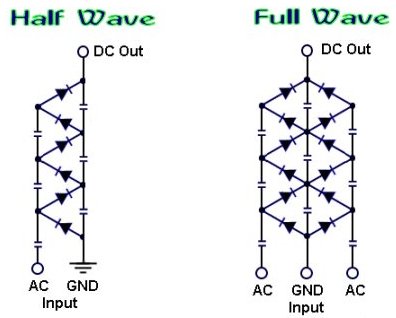
Something like the half wave circuit in the image is what I'd like to use but
I could generate a square wave ac pulse and use the full wave circuit if
the efficiency would be a lot better. I'm just not sure...I'm a software person
not a hardware guru. I would have about 3v in to the half wave circuit
or about 6v peak to peak to the full wave.

this using the 3.3v supply powering my prop circuit. I have a 3.3v
at 1amp switcher powering the prop so 300ma should not tax it too
hard. Would simply switching a small signal transistor on/off using
an I/O pin and creating a pulsed dc waveform into a voltage multiplier
circuit work? Or would it be better to create square ac pulses? I would use
a 24v linear regulator and a large cap at the end of the multiplier
circuit.
Super efficiency is not a concern as this circuit won't run that often
or for long periods. I was just going to put a 300ma load on the 24v
regulator and watch the 3v line going into the multiplier circuit with
a multimeter and fine tune the pulse frequency and duty cycle for
minimum ma. If anyone has any suggestions for best duty cycle and
rate that would be nice. Also what type caps would you guys use in
the multiplier circuit? I'm planning on using 1N4007 diodes and a 1000uf
cap as the filter.
Something like the half wave circuit in the image is what I'd like to use but
I could generate a square wave ac pulse and use the full wave circuit if
the efficiency would be a lot better. I'm just not sure...I'm a software person
not a hardware guru. I would have about 3v in to the half wave circuit
or about 6v peak to peak to the full wave.
396 x 318 - 21K
Comments
Second, getting to 24v from 3.3 will need 7 or more stages. At 300ma a 7 stage multiplier will draw ~2.1 amps. This is way more power than your regulator for the propeller can provide. How much voltage do you have feeding the prop's regulator? Is this voltage fairly stable? It may be worth it in this case to get a 1/2 H-bridge chip and drive the voltage multiplier directly from the external power supply. You can then regulate the output of the multiplier by pausing the drive frequency whenever the output voltage is too high. (switched capacitor circuits act like resistors at "low" frequencies)
If you only need 10-30mA this Charge_pump circuit will work directly from an open bank of propeller pins. (or any other logic chip for that matter. Several 74C14 chips in particular can build up 100's of volts when run at 12-15 Vcc)
Lawson
Thanks Mike, I did not know that it would take over 2 amps at 3.3 to
give me 300ma out at 24v. I just saw some data about multiplier circuits
and thought it might be a fast way to get to 24v without needing a
transformer. My 3.3v switcher can take up to 40v in and give me 1amp
out at 3.3 so I guess one solution is to string 20 sub-c nimh cells together
to get the 24 directly for the sensor and also feed the 24 to the switcher
for the 3.3v. I had hoped I could somehow power this project directly
from a 7vdc source available at the site and not need batteries in it. Maybe
I can figure a way to use capacitors to somehow hold enough charge
to power the sensor for short bursts instead of the batteries...hmmm, but
how to charge them from either the 7v source directly or the 3.3v regulated
source. Perhaps some sort of setup where 4 caps are charged to 7v each
and then connected together with an I/O pin controlled set of transistor
switches to deliver roughly 28v to the sensor then switched back to each
soak up and hold another 7v charge until they are again needed to power
the sensor. I though maybe the power supply circuit would be easy to do...silly me :-)
@Lawson
The charge pump idea is interesting. Also using better diodes is a smart idea.
The source of power is 7vdc. I will try putting it under a 2.5amp load and see
what happens to the voltage, whether it drops or remains stable.
BTW, the sensors that run on 24v are small units that send out microwave pulses
and detect the return echo from a distant object. You control them using a set
of data lines from a uc. It's a kind of short range radar system. They are small round
devices with a white ceramic front and a metallic back where the data and power
socket is located. Your software can send requests to the sensor to send out an
rf ping of variable power and 2 selectable beamwidths. The data from the return
echo is a block of data detailing stuff like proximity and speed. The sensors are
pretty smart and must contain a capable uc inside, the data manual for them lists
quite a few commands you can send and you can get all sorts of data back from them.
I guess I could use a voltage multiplier circuit with a 1000uf cap for a filter
and a linear regulator in constant current mode to charge the batteries at
a low level like 25ma. As Lawson said I could use the 7v as input to the
multiplier instead of the 3.3v.
I downloaded the PDF manual for the BumbleBee and it would be quite useful
for many projects.
The sensors I have are mil surplus from a recent project, the parts didn't perform
as well as they needed to so I and a few others got to take them home to see
what we could come up with. I have several projects in mind, one is a remote
unit using a radar sensor and a uc hooked to a small cmos camera. The idea
is to detect small objects thrown by a person and snap a photo of them. I have it
working, sort of. I currently have it connected to a cheap keychain cmos camera
that takes low-res images at 640x480 but if I get it working really well I will get
some better cams. I need to add several powerful IR LEDs to enable images
in the dark. 24v is a pretty common voltage for mil surplus parts to work on..I
don't know why.
This article might not be what you want because it doesn't supply all the voltage you need but it might give you other ideas.
http://dangerousprototypes.com/2011/03/04/1-5-to-10-volt-inverter/
Chuck
Would this need to be a continuous supply of 24V @ 300mA or an intermittent supply? The responses so far have been for continuous supplies, but it is possible if you were only needing that voltage in intermittent 'bursts' that you could get away with less constant demand on your source.
For example... for steady operation it has been determined that you need at least 3.3V @ 2.2 Amps.
24V@300mA = 7.2 Watts
3.3V@2.2A = 7.26 Watts
If you only needed the 24V@300mA for 1/4 of the time then the demand on your source would only need to be 3.3V@545mA... 1/10th of the time would require 3.3V@218mA from your source.
You are correct, of course. However, from a practical standpoint, it also depends on how long each 25% or 10% duty cycle lasts and how much energy can be stored in the interim. If the duty cycle is five milliseconds every fifty milliseconds, a large cap could do the job. But it it's five seconds every fifty seconds, a cap would be insufficient; it would take a battery. Without that, you'd still need to provide the full current.
-Phil
the sensor send continuous pulses at its lowest output power and just
using a multimeter to see what the current draw was. When pulsing it
hovered around 300ma but when it was just awaiting commands it drops
down to about 40ma. I think it may have some small caps internally that it
charges and then uses them to power the pulses because at high power
if you send single pulses it draws a lot of current before and after the first pulse
but if you then send a second pulse a few seconds later the current stays
at about 40ma so I figured it was using the stored energy to make the 2nd pulse.
Just an idea, if you are interested I can post more descriptive information here, or someone who knows more about it than me perhaps can as well.
Either way, good luck!
Derrick