

Controlling Relay
 txaggie
Posts: 26
txaggie
Posts: 26
Hello all!
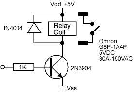
I am trying to control a relay and have the circuit working, but wanted to make sure that I have it setup correctly. Obviously protecting the IO on the stamp is the main concern. I have attached the circuit diagram. Could anyone please tell me if this will work as-is or if there is a better way to hook it up?
I had to play with the resistor value to get it low enough to switch the transistor. I started out with 100K, then 10K and finally the 1K worked. As you can tell, I am not that savvy with electronics.
I currently have it hooked up to P2 and when I set HIGH 2, it turns the relay on.
Thanks,
Scott
276 x 190 - 40K
Comments
Thanks so much for your reply! I really appreciate your answer. You "have given me a fish for a day"! Is there any way you can explain how you came up with that answer and "teach me how to fish for a lifetime"? As easy as it may be for me to take your answer and move on, I am the type of person who truly wants to know why your answer is the correct way. To be honest, the schematic I posted was from various resources on how to control a relay. I just pieced them together as to what I thought was "correct". I understand to a degree how the transistor operates as far as switching based on current. I just don't understand what the current is I am targeting. Do you mind explaining how you got the 4mA current that is past through the 1K resistor (I have looked through the stamp's datasheet, and haven't quite found out what each IO is capable of sourcing)? Also, why is 330 or 470 Ohms more appropriate and why is 120 mA more than necessary? If the gain is 30, as you say is a reasonable value, what current should I be looking for?
I hope that I am not asking too much from you! I try not to be too dependent on other people and enjoy figuring things out on my own, but as it pertains to electronics, I am finding myself asking questions quicker than google can give me answers. Maybe I am getting too old for a hobby that requires more background knowledge than I have time to learn
Thanks again,
Scott
Look in the same datasheets to see what the I/O pins can supply in the way of current.
"120 mA" - 30 is a nice round number, not unusual for a general purpose switching transistor's gain. I figured that a smallish relay would draw maybe 100mA ... that's 1/2 Watt at 5V. I was too lazy to look up the relay you showed, so I made an educated guess. Again, look in the datasheet for the coil current for the relay. You want the transistor to have enough base current so that it can provide more current than the relay needs even though the relay will only draw as much current as it's made for. This ensures that the transistor is saturated (look this up on the Wikipedia) so it will have a voltage drop across it of maybe 0.3V and will dissipate the least heat.
Remember ... study the datasheets for the devices you're using and "the Wikipedia is your friend".
btw, this is called a "pulldown resistor" since it holds the switch's (transistor's) input low as long as there is not input high from the signal source.
-Tomato
If you were using an MOSFET instead of the junction transistor, you would need a pulldown. An MOSFET has a high impedance gate which is voltage triggered and you need a pulldown resistor to provide a default voltage for the gate.
Thanks again,
Scott
That is true, but in my experience i find that switching is cleaner with the pulldown resistor even with BJTs. Not crucial at all for switching on a relay, but i say why not just toss it in.
-Tomato
-Tomato
I have finally gotten to the stage of testing my breadboarded circuit. I have made the changes to the design as suggested. Everything worked perfect until I ran 120VAC through the relay contacts. When I hook up 120VAC into the line and load of the relay contacts, my Stamp board of education resets when I turn the relay on. I initially thought it was the load that the modified power cord was plugged into, but when I removed the actual load to just switch the 120VAC the same thing happened. The 120VAC is not even present on the board (I have used a separate breadboard for all of my core circuitry including the relays). I have the part of the relay with the contacts hanging off the side of the board. The relay is sound, as we use it on our commercial PCB (the difference being, we used a professional engineering company to do all the engineering work). Any suggestions as to why this could be happening?
I am baffled by this... and certainly dont want to do anything to jeopardize my BS2px!!!!
Here are the appropriate data-sheets for the relay and transistor.
Thanks,
Scott
14 more to go!!!!!
-Scott
If it's an AC/transformer-based supply, it'd better be isolated. If it wasn't isolated and/or you have a hot-chassis (because of a line/neutral/safety-ground swap), then things could get interesting.
A picture of your set-up may prove useful.
What's your coil current? That MPS8099 let's you suck down 500mA, but the relay datasheet says that at 5VDC, you shouldn't be pulling more than 185mA through the coil. The fact that you were having problems (and ended up frying an I/O) even with no load, suggests to me that you are sucking down too much current through that relay. If you can give the exact circuit ur using that would be helpful, because too much coil current (ie, collector current) could mean too much base current...maybe that's how you fried your pin.
-Tomato
Thanks for your replys. I am using the exact circuit I posted except i am bringing the io off the BOE onto a seperate breadboard and the BOE is being powered with a 6V wallwart. I am not sure what you mean about isolation. I have pretty much removed everything else so that is basically the only circuit. The relay worked fine prior to soldering the 120VAC power cord to the contacts and then trying to switch it with or without any actual load. I know the BOE uses the internal vreg on the bs2 instead of the external regulator. How can I isolate that? Regarding the current of the transistor, what should I be looking for when searching the endless supply of NPN transistors?
Thanks,
Scott
I will be able to post some pictures In an hour! Hopefully you can make sense of it. Also, I NEVER claimed that I was doing everything right, only that I set it up as suggested to me earlier in this post. Trust me, this isn't a situation where it would be possible to hurt my feelings. I am more interested in doing this correctly and learning from the experience!
Thanks for taking the time to help me!
-Scott
Thanks,
Scott
Looks like the wire from the base to the base resistor on the Parallax board is off / wrong row.
Thanks so much for your assistance. I will re-test this afternoon and let you know the results!
Thanks,
Scott
Basically what I am trying to make is a Ni-Cd battery auto-cycle circuit that will cycle between the charging rail (it is a battery rejuvenater that works awesome. I have brought several Dewalt battery back from the dead) , discharging rail and a state of rest. To rejuvenate these batteries, you have to charge them and discharge them several times to bring the battery back to full life and sometimes better than new.
The top left of the main breadboard is the leads coming from the battery (+ on the left, - on the right) the lower left is the +5V from the BOE used to run the relays. The lower right is the discharge rail and the top right is the charge rail. The top white relay controls whether the battery is resting (NO) or charging/discharging (Closed) based on the bottom white relay (NO - discharging, Closed - Charging). When I give the micro-controller the command to charge, I close the lower white relay to make sure it is on the charging rail, close the top white relay to connect the battery, then turn the big relay on that turns the charger on (the charger states that there must be a battery hooked up prior to turning the charger on, hence the need for the big relay). I also have an ADC (MCP3204) hooked up so I can plot the voltage change in the battery and also to know when to remove the battery from the discharge rail. Everything is controlled by software that I wrote that sends commands to the micro-controller as to what to do. A cycle consists of discharging the battery down to 9VDC, let it rest an hour, then putting it on the charging rail. I am using the LED from the charger for an input to the micro-controller to let the software know when charging is complete.
The problem is when I put the battery on the charging rail. That's when the BOE resets. I close the bottom relay (charging rail), close the top relay (connects battery to charging rail) and then turn on the big relay (turns on charger). Currently, I don't actually have the battery connected or the charger connected because I am just testing the logic and now trying to troubleshoot the reset. I am pausing 2000 ms between each relay command so I can hear them each individually close. As soon as the big relay closes, the BOE resets. If I remove the transistors for the bottom two relays, essentially removing the relays from the circuit, the big relay turns on with no problems. So obviously the issue lies with have all relays closed at the same time. If I was to throw a dart, I would say the grounding isn't good enough to sink all the current going through the transistors.
Any ideas??? Let me know if I need to clarify anything...
Thanks,
Scott
EDIT: I removed one of the transistors from one of the bottom two relays and everything worked, so the issue is have all 3 relays closed at the same time.
Thanks,
Scott
You have those 5V relays and they suck 200mA each, and 3 suck 600mA, and that's probably too great a demand on your power supply. There's a big surge at first turn on, too. I figure that heavy load is taxing your power supply which results in a "brown out", "resetting" the Stamp. You may be at or near the on-board regulator's max and/or that of your wall-pack.
What's the rating of that wall-pack?
The wallwart is only rated for 300mA.
Thanks,
Scott
Thanks,
Scott
You have less 1/3 base current that way.
EDIT -- If that makes the difference you're getting by by the skin of your teeth. You need to beef up that supply because it's "super marginal".
Edit 2 -- 15mA is a lot of base current, 5 ought to do it, but still, you need more oomph.
So you are recommending me to keep the 330 Ohm resistor values for the transistors and then use a beefier power supply to give me more mA overhead, correct? I am definitely gonna use a bigger supply, but just want to confirm the resistor.
Thanks,
Scott
I asked whether using 1K resistors made the difference: that you were then able to kick all three relays on.
Using 1kΩ results 5mA of base current, lower overall current demand on your marginal power supply.
I think that 15mA, by using the 330Ω, is a lot of base current; as far as I'm concerned it's too much (unnecessary.)
If you have a DVM then set it up to measure Volts from your V_in and you'll be able to see it go lower and lower with each relay that you actuate. Using the ammeter would be instructive, too.
You need, it seems to me, a heftier power source.
Results using 9VDC power supply and 330 Ohm resistors:
DVM:
Vin: 9.3 VDC
Vin, 1 small relay on: 9.22 VDC
Vin, 2 small relays on: 9.14 VDC
Vin, All relays on: 9.05 VDC
Ammeter results: (based on initial draw)
Initial power on: 83 mA
1 relay on (small relay): 133 mA (126 mA using 1K resistors)
2 relays on (both small relays): 186 mA (170 mA using 1K resistors)
all relays on: 384 mA (358 mA using 1K resistors)
Results using 6VDC power supply and 1K Ohm resistors:
DVM:
Vin: 6.07 VDC
Vin, 1 small relay on: 6.05 VDC
Vin, 2 small relays on: 6.03 VDC
Vin, All relays on: 5.89 VDC
Ammeter results: (based on initial draw)
Initial power on: 83 mA
1 relay on (small relay): 126 mA
2 relays on (both small relays): 165 mA
all relays on: 265 mA (roughly, I had to use an analog ammeter b/c the digital caused it to brown-out)
Thanks,
Scott
That way you're lean & mean and you'll have more power left for other stuff.