

Drive X and Y stepper motor with propeller Demo Board
 NikosG
Posts: 705
NikosG
Posts: 705
Hello all,
This is my first attempt to drive two stepper motors using the propeller microcontroller. This activity is a part of a bigger project which is in the pipeline and I would like to make clear in advance that this is an experimental approach and it is very possible to need various improvements.
Although I have some experience driving stepper motors with custom and home-made electronics Im a new propeller user and it is very possible to discover that I have done some mistakes. So Im waiting for your advice and your suggestion if you notice something wrong or something that I need to improve.
Here is the hardware I have used:
1) The motors I have used are two unipolar stepper motor very similar to 4-Phase /12-Volt Unipolar Stepper Motor (#27964) from parallax store. I also found two gear boxes for these motors which will help me a lot to finish my future project.
2) I also use a ULN2803A Darlington Array.
The reason I used the ULN2803A chip instead of the ULN2003 chip is because the ULN2803A chip is able to drive simultaneously two stepper motors. This choice is also suggested by the stepper motors manual.
3) The propeller board I have used is the Propeller Demo Board.
This board is ideal for my application as it is very friendly for a new propeller user like me because it provides a lot of facilities such as the breadboard, TV & VGA out and the two PS/2 connectors for mouse and keyboard I/O essential for the data input.
4) I also used a battery 9,6V to power the two stepper motors and a 7, 5 Volt 0, 7 Amp Power Supply to power my Propeller Demo Board.
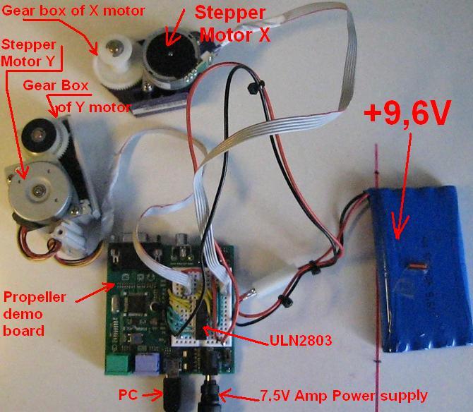
Here is a photo of the hardware which is described above:

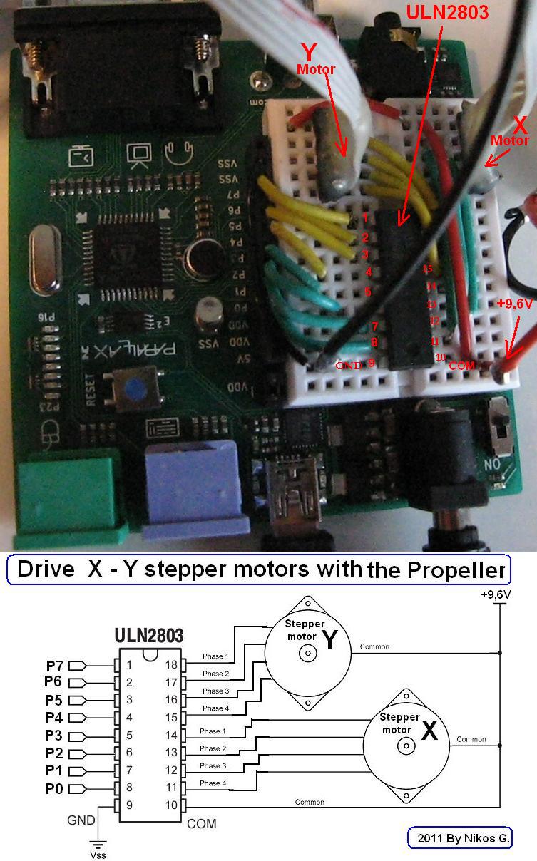
The schematic I have used is the following:

The code I have used is a very simple code that is based on the following idea:
To rotate a 4-Phase Unipolar Stepper Motor whose its phases 1,2,3,4 are connected to the P0,P1,P2,P3 Pins of the propeller microcontroller is exactly the same as you try to blink four LEDs light with sequence which are connected to the P0,P1,P2,P3 Pins.
So here is the code to rotate a unipolar stepper motor:
Trying to drive simultaneously and a second stepper motor (the Y-motor) I have used the multitasking ability that offers the propeller microcontroller.
The code for this task is the following:
And here is something that I can't explain and I need your help.
As you can see in the previous video when the Propeller demo board is connected with the PC the stepper motor rotates continuously. When I disconnect the Propeller demo board from the PC the stepper motor rotates for some seconds then stops for a little while and then rotates again and repeat the same procedure.
I cant explain yet why this it happens.
If anyone can help is welcome!
Thank you,
Nikos Giannakopoulos
This is my first attempt to drive two stepper motors using the propeller microcontroller. This activity is a part of a bigger project which is in the pipeline and I would like to make clear in advance that this is an experimental approach and it is very possible to need various improvements.
Although I have some experience driving stepper motors with custom and home-made electronics Im a new propeller user and it is very possible to discover that I have done some mistakes. So Im waiting for your advice and your suggestion if you notice something wrong or something that I need to improve.
Here is the hardware I have used:
1) The motors I have used are two unipolar stepper motor very similar to 4-Phase /12-Volt Unipolar Stepper Motor (#27964) from parallax store. I also found two gear boxes for these motors which will help me a lot to finish my future project.
2) I also use a ULN2803A Darlington Array.
The reason I used the ULN2803A chip instead of the ULN2003 chip is because the ULN2803A chip is able to drive simultaneously two stepper motors. This choice is also suggested by the stepper motors manual.
3) The propeller board I have used is the Propeller Demo Board.
This board is ideal for my application as it is very friendly for a new propeller user like me because it provides a lot of facilities such as the breadboard, TV & VGA out and the two PS/2 connectors for mouse and keyboard I/O essential for the data input.
4) I also used a battery 9,6V to power the two stepper motors and a 7, 5 Volt 0, 7 Amp Power Supply to power my Propeller Demo Board.
Here is a photo of the hardware which is described above:
The schematic I have used is the following:
The code I have used is a very simple code that is based on the following idea:
To rotate a 4-Phase Unipolar Stepper Motor whose its phases 1,2,3,4 are connected to the P0,P1,P2,P3 Pins of the propeller microcontroller is exactly the same as you try to blink four LEDs light with sequence which are connected to the P0,P1,P2,P3 Pins.
So here is the code to rotate a unipolar stepper motor:
CON

  _CLKMODE      = XTAL1 + PLL16X
  _XINFREQ      = 5_000_000

waitPeriod = 2_000_000 ' 1/2 sec switch cycle
 ph1Pin_x = 0    ' phase 1 control pin  for X motor
 ph2Pin_x = 1    ' phase 2 control pin  for X motor
 ph3Pin_x = 2    ' phase 3 control pin  for X motor
 ph4Pin_x = 3    ' phase 4 control pin  for X motor


 smv = 5   ' stepper motor velocity  1= min, 10 =max

OBJ
   pst: "Parallax Serial Terminal"

PUB Main
  if(ina[31])
   pst.Start(57600)
dira[0..3]~~
outa[0..3]~

  repeat
    ROTATE_X_MOTOR

PRI ROTATE_X_MOTOR
 if(ina[31])
  pst.str( string("X---1",13))
 !outa[ph1Pin_x]
  waitCnt(waitPeriod/smv +cnt)
  !outa[ph1Pin_x]

  if(ina[31])
   pst.str( string("X---2",13))
 !outa[ph2Pin_x]
 waitCnt(waitPeriod/smv+cnt)
 !outa[ph2Pin_x]

 if(ina[31])
   pst.str( string("X---3",13))
 !outa[ph3Pin_x]
 waitCnt(waitPeriod/smv+cnt)
 !outa[ph3Pin_x]

 if(ina[31])
   pst.str( string("X---4",13))
 !outa[ph4Pin_x]
 waitCnt(waitPeriod/smv+cnt)
 !outa[ph4Pin_x]
Trying to drive simultaneously and a second stepper motor (the Y-motor) I have used the multitasking ability that offers the propeller microcontroller.
The code for this task is the following:
CON
_clkmode = xtal1 + pll2x
 _xinfreq = 5_000_000 'Note Clock Speed for your setup!!

 waitPeriod = 2_000_000 ' 1/2 sec switch cycle
 ph1Pin_x = 0    ' phase 1 control pin  for X motor
 ph2Pin_x = 1    ' phase 2 control pin  for X motor
 ph3Pin_x = 2    ' phase 3 control pin  for X motor
 ph4Pin_x = 3    ' phase 4 control pin  for X motor

 ph1Pin_y = 4    ' phase 1 control pin  for y motor
 ph2Pin_y = 5    ' phase 2 control pin  for y motor
 ph3Pin_y = 6    ' phase 3 control pin  for y motor
 ph4Pin_y = 7    ' phase 4 control pin  for  y motor
smvX = 8' 10 'steper motor velocity 1= min
 smvY = 8' 10 'steper motor velocity 1= min
VAR
     LONG STACK[30]
OBJ
   pst: "Parallax Serial Terminal"

PUB Main
  pst.Start(115200)
  dira[0..7]~~
  outa[0..7]~
  COGNEW (ROTATE_Y_MOTOR,@STACK)
  repeat
    ROTATE_X_MOTOR
    ROTATE_Y_MOTOR


PUB ROTATE_X_MOTOR

!outa[ph1Pin_x]
  waitCnt(waitPeriod/smvX +cnt)
  !outa[ph1Pin_x]


 !outa[ph2Pin_x]
 waitCnt(waitPeriod/smvX+cnt)
 !outa[ph2Pin_x]

 !outa[ph3Pin_x]
 waitCnt(waitPeriod/smvX+cnt)
 !outa[ph3Pin_x]

!outa[ph4Pin_x]
 waitCnt(waitPeriod/smvX+cnt)
 !outa[ph4Pin_x]

PUB ROTATE_Y_MOTOR
!outa[ph1Pin_y]

 waitCnt(waitPeriod/smvY +cnt)
  !outa[ph1Pin_y]

!outa[ph2Pin_y]
 waitCnt(waitPeriod/smvY+cnt)
 !outa[ph2Pin_y]

!outa[ph3Pin_y]
 waitCnt(waitPeriod/smvY+cnt)
 !outa[ph3Pin_y]

  !outa[ph4Pin_y]
 waitCnt(waitPeriod/smvY+cnt)
 !outa[ph4Pin_y]
The following video displays the stepper motors running the codes described above.
And here is something that I can't explain and I need your help.
As you can see in the previous video when the Propeller demo board is connected with the PC the stepper motor rotates continuously. When I disconnect the Propeller demo board from the PC the stepper motor rotates for some seconds then stops for a little while and then rotates again and repeat the same procedure.
I cant explain yet why this it happens.
If anyone can help is welcome!
Thank you,
Nikos Giannakopoulos
753 x 1208 - 148K
670 x 584 - 72K
Comments
FWIW: Here's my old code for full, half, quarter, and micro stepping the Parallax unipoloar steppers in a similar setup:
http://www.rayslogic.com/propeller/Programming/Stepper/Stepper1.zip
But, I realize now that microstepping should actually apply a sinusoidally varying current in steps and not a linearly varying current like I did...
@ Rayman I downloaded your code and I'll try it later. Thank you!
@ Jon Thank you for your correction!
Do you see something wrong in the first code which manipulate only one stepper?
When I use this code (for the one stepper) and disconnect the Propeller demo board from the PC the stepper motor rotates for some seconds then stops for a little while and then rotates again and repeat the same procedure. Why? could you explain this please?
But you have scared me! what exactly is this FTDI reset??? Do I have something like virus in my propeller?
If the USB cable is removed, this powers up the FTDI chip which then immediatly resets the Prop...
I think that I'will have a lot of question at the "Propeller Meetup Group" on Fri, Feb 25, 2011 !!!!!!
Anyway! Thank you all of you!!!
You are fantasic people!!!
I think the simplest software fix is to test P31 for logic 1 before starting the FullDuplexSerial driver.
If the USB cable is connected, it should be asserting power on P31 otherwise it seems to float low...
... etc.
I should create a new programe?
How can I start a driver? The "startDriver" you mentioned above is a command?
Could you give me more details please?
the converter you mentioned above is the Parallax USB to Serial (RS-232) Adapter or another product?
the propeller-demo-board has already an FTDI-Chip on board.
Kye meant this onboard FTDI-Chip.
your codelines like
[FONT=monospace]
  [/FONT]pst.str( string("X---1",13))
sends serial data towards the onboard-FTDI-chip. The onboard-FTDI-chip converts the serial datastream coming from the propeller into a USB-datastream going to your PC.
if you try to send serial data when the USB-cable is DISconnected this will cause a reset of the propeller-board.
After a reset the program is loaded new from the EEPROM-chip (which needs some seconds) and then the program starts running again.
As a quick check if this is the case comment out EVERYTHNING that has to do with "PST"
If the steppermotors then behave normal you now it is the ONBOARD FTDI-chip
Anyway I recommend a dual way of learning:
reading the manual about the propeller-chip and as soon as a question arises post this question in the forum
this way you will climb up the learning-curve and get a deeper understanding of how it works.
start playing with adding your own debug-output.
If you know how to add debug-output this output will make it MUCH easier to understand what your code actually does
best regards
Stefan
Comment out some code will be a temporary solution and thank you for this!
But the solution suggested above by Kye and Ryman I think is more proper and my first question still remains. I’m saying this because I’ll need "PST" commands to complete my project and I can’t comment out them permanently for ever.
However thank you very much for your solution and for your kind suggestion.
I know some times I’m trying to solve problems beyond my level but all these amazing Propeller abilities have really seduced me!!!!
I ask your understanding if some of my questions sounds inaccurate and absurd.
Nikos.