

Help with HM55B Compass Module
 clamb
Posts: 7
clamb
Posts: 7
Hi All,
I am trying to read angles from the compass module. I have wired and calibrated as shown in the manual. However when i run the "test calibrated sensor program" , the values shown on the debug terminal jump all over the place with differences as much as 43 degrees apart. The same thing happened even before I calibrated.
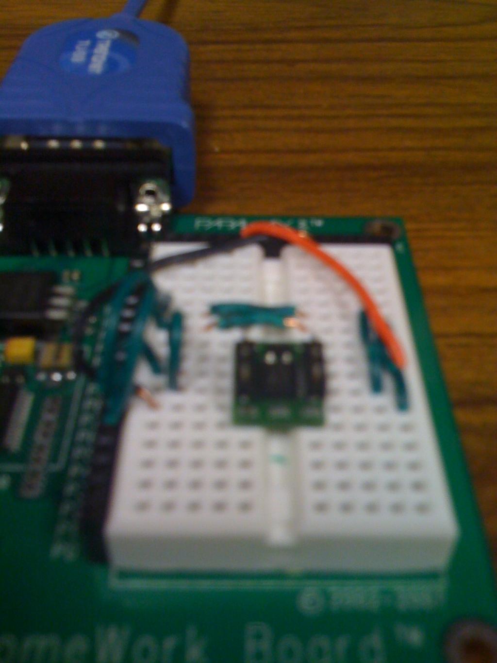
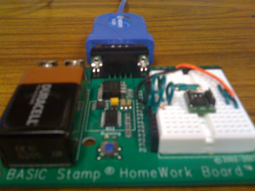
I am using a BS2 Rev E board. Below is an attached picture of my circuit. Does anyone know why this might be happening cos I have exhausted all my possible reasons. Thank you.
I am trying to read angles from the compass module. I have wired and calibrated as shown in the manual. However when i run the "test calibrated sensor program" , the values shown on the debug terminal jump all over the place with differences as much as 43 degrees apart. The same thing happened even before I calibrated.
I am using a BS2 Rev E board. Below is an attached picture of my circuit. Does anyone know why this might be happening cos I have exhausted all my possible reasons. Thank you.
1024 x 1365 - 98K
1024 x 768 - 71K
Comments
Dave
After reading your reply I decided to explore 2 possibilities: 1) Something about my test location makes it go crazy. 2) My battery voltage isn't strong enough
TEST LOCATION:
There are no magnets around me but I moved my testing to another location and the values on the debug terminal were generally less erratic but still wavered considerably.
BATTERY VOLTAGE (At new location):
I measured the voltage from my 9V battery using a digital multimeter. It read 8V. As a control, I fed 9.2v to the basic stamp board using a DC power supply. Here are the results:
With the Battery, on the average there was a difference of 3 degrees in values observed on the debug terminal and an extreme of 7 degrees every once in a while.
With the Dc power supply, on the average there was a difference of 3 degrees in values and an extreme of 7 degrees every once in a while.
My application requires a high degree of accuracy at all times. Is it normal to have a difference as high as 5 degrees?
If I borrowed some principles from Electromagnetics to build a shield for the compass against magnetic fields (to reduce fluctuation), would this render the compass useless being that the core of its functionality is a magnetic sensor?
Given that the compass actually measures the field strength and converts to compass angle, it's very sensitive to small field changes in areas of the compass circle where the X value is near zero and you can get large jumps with small magnetic field changes.
A magnetic field shield would shield the compass from just the signal you're trying to measure. If there are motors or large conductors nearby, you need to shield those or move the sensor away from them. There's a square law effect and small distance changes can have large effects when the compass is close to an interference source.
To Me, that translates into..
You only get 64 positions out of a possible 360.. So there might be a little jitter in the compass heading.
I have not tried to run the heading thru a Kalman Filter, I wonder if that would help the heading jitter's?
You know, the same type of code that Makes PID work with Prop Bots.. it smooths out the servo movements.