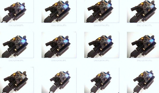
Penguin B Numbers - Using the New Display
"Penguin B" Numbers Display Program
Control the seven segment display with just three lines
instead of four, using the 74HC595 Serial In Parallel Out
shift register

I wrote several Penguin B programs for the new display a year
ago and just took some time diversion from the Brain project to
update the code. The first code presented is a number and decimal
point program. Other programs will follow for text messages,
graphics, and the English alphabet. The code comments show
clearly how the characters are generated and a display driver is
included along with a timer, output stabilizer, screen blanker
and latch.
penguinb_numbers.bpx
The second program is similar except the numbers appear in a loop.
penguinb_numbers_continue.bpx
Control the seven segment display with just three lines
instead of four, using the 74HC595 Serial In Parallel Out
shift register
I wrote several Penguin B programs for the new display a year
ago and just took some time diversion from the Brain project to
update the code. The first code presented is a number and decimal
point program. Other programs will follow for text messages,
graphics, and the English alphabet. The code comments show
clearly how the characters are generated and a display driver is
included along with a timer, output stabilizer, screen blanker
and latch.
penguinb_numbers.bpx
The second program is similar except the numbers appear in a loop.
penguinb_numbers_continue.bpx
' The attached program has all the tools necessary to count numbers
' from 1 through 9 and show a decimal point for making fractional numerical
' representations. It also calculates the decimal value and shows it
' on the Debug screen. This is handy if you prefer to work with
' decimals instead of binary numbers. The code comments simplify the
' method for creating additional characters using the Binary number
' approach. See other Humanoido programs for Penguin to create text
' messages, reproduce the English alphabet and make graphic characters.
'
' The idea is to control the seven segment display with just three lines
' instead of four, using the 74HC595 "serial in parallel out" shift register.
' I'm happy to say the idea has come to frution. The 74HC595 design converts
' a synchronous serial data stream to eight parallel outputs, namely seven
' segments and one decimal point.
'
' The synchronous serial data has components to program, mainly the serial
' data and the serial clock. The SHIFOUT command is chosen to handle these
' details and write data to the synchronous chip. After the shifting process,
' the data must be latched to the outputs by momentarily pulsing the Latch
' control line. This will stabilize the outputs as new data is shifted in,
' and is accomplished with a PULSOUT statement. Shiftout is LSB least
' significant bit first.


