Shop OBEX P1 Docs P2 Docs Learn Events
Get your Penguin working without modifing the circuit card. — Parallax Forums

Get your Penguin working without modifing the circuit card.

zappmanzappman Posts: 418
edited 2011-03-28 02:25 in Robotics
Get your Penguin working without modifing the circuit card.
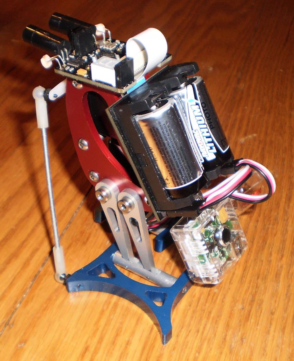
My Penguins arrived on 2/18/2011, the first has been put together & is roaming across the floor untethered.
I have not made the changes to the circuit cards.
I am using a tiny battery that I got on clearance at Radioshack, it is made to power USB devices like a cell phone.
It fits just right and works great on the Penguin.
The penguin I put together is Red with Blue feet.

P2190310cropped.jpg


Digipower Jumpstart Instant Charger - JS1-V3
attachment.php?attachmentid=1386&d=1298151691&thumb=1attachment.php?attachmentid=1384&d=1298151689&thumb=1attachment.php?attachmentid=1383&d=1298151688&thumb=1attachment.php?attachmentid=1385&d=1298151690&thumb=1
Product Summary
Manufacturer: DigiPower
Mfg Part#: JS1-V3
Buy.com Sku: 211342958
UPC: 758302627806
UPC 14: 00758302627806

Features
dot2.gifProduct Type Battery Charger
dot2.gifManufacturer Part Number JS1-V3
dot2.gifManufacturer Website Address www.mizco.com
dot2.gifManufacturer Mizco International
dot2.gifProduct Name Jumpstart Instant Charger
dot2.gifBrand Name DigiPower
dot2.gifOutput Voltage 5 V DC

www.buy.com price is $7.50 + $2.99 shipping = $10.49

http://www.buy.com/prod/digipower-so...211342958.html

I purchased mine on clearance from Radioshack Item # 23000929 for $1.97

MATERLAL SAFETY DATA SHEET
http://www.radioshack.com/graphics/uc/rsk/Support/MSDS/2300929_MSDS.pdf
1024 x 1257 - 170K
«1

Comments

  • Martin_HMartin_H Posts: 4,051
    edited 2011-02-19 16:16
    With my penguin I found I could pull the USB cable out once the program started running. Have you tried that with this battery?
  • zappmanzappman Posts: 418
    edited 2011-02-19 16:34
    Martin_H wrote: »
    With my penguin I found I could pull the USB cable out once the program started running. Have you tried that with this battery?

    You use this battery in addtion to the normal batteries the Peguin uses.
    Using the additional battery is the same as having the the Penguin pluged into the USB port, for power purposes.
    You can turn the Penguin on and off as many times as you want, and it always works.
    Just remember to unplug the USB battery when you are not using the Penguin so it does not discharge the USB battery.
  • doggiedocdoggiedoc Posts: 2,240
    edited 2011-02-19 16:46
    That's a nice "low tech" fix! I haven't attempted the circuit repair yet.... kinda thinking I need better magnification!!

    Paul
  • HumanoidoHumanoido Posts: 5,770
    edited 2011-02-19 18:33
    Zappman, thanks for showing us your customized red and blue Penguin with the added "USB battery" when combined with the regular Penguin photo batteries delivers enough power so a motherboard mod is not needed. Brilliant!

    We could probably DIY a small plug and added battery, to plug into Penguins USB connector to give it the edge is power boost.
  • Martin_HMartin_H Posts: 4,051
    edited 2011-02-19 21:26
    Well I attempted the re-work and it ended in disaster. I was able to cut the trace and solder the second resistor, but was unable to get a good contact with the third component. Then surface tension pulled the resistors with the soldering iron. The heat seemed to melt the solder mask over the pads and I couldn't find them to solder the resistors back down.

    After several hours of unsuccessful attempts, gave up. So I tried to run a jumper directly from pin 1 on the FTDI chip. I accidently pulled on the jumper and pulled pin 1 off the FTDI chip. So I guess the battery board is trash now.

    So for the second penguin I'm going to try something like this. I consider myself reasonable with soldering, but these parts are too small, and the margin for error seems like its zero.

    Any ideas for the broken penguin? The body is in good shape, as is the BS2 board on top.
  • WBA ConsultingWBA Consulting Posts: 2,934
    edited 2011-02-19 22:06
    Martin, sorry to hear how things worked out for the rework. I have a few left over from making the rework instructions so PM me your address and I'll send you two reworked boards to swap for your two.
  • HumanoidoHumanoido Posts: 5,770
    edited 2011-02-19 22:10
    Martin_H wrote: »
    Well I attempted the re-work and it ended in disaster. I was able to cut the trace and solder the second resistor, but was unable to get a good contact with the third component. Then surface tension pulled the resistors with the soldering iron. The heat seemed to melt the solder mask over the pads and I couldn't find them to solder the resistors back down.
    After several hours of unsuccessful attempts, gave up. So I tried to run a jumper directly from pin 1 on the FTDI chip. I accidently pulled on the jumper and pulled pin 1 off the FTDI chip. So I guess the battery board is trash now.
    So for the second penguin I'm going to try something like this. I consider myself reasonable with soldering, but these parts are too small, and the margin for error seems like its zero.
    Any ideas for the broken penguin? The body is in good shape, as is the BS2 board on top.
    Martin, thanks for describing your experiences with board repair. I can see how that can happen so don't feel bad. This opens up a new window of opportunity to put a propeller chip on the Penguin chassis and reuse the battery holder.
  • zappmanzappman Posts: 418
    edited 2011-02-19 22:17
    Martin_H wrote: »
    Well I attempted the re-work and it ended in disaster. I was able to cut the trace and solder the second resistor, but was unable to get a good contact with the third component. Then surface tension pulled the resistors with the soldering iron. The heat seemed to melt the solder mask over the pads and I couldn't find them to solder the resistors back down.

    After several hours of unsuccessful attempts, gave up. So I tried to run a jumper directly from pin 1 on the FTDI chip. I accidently pulled on the jumper and pulled pin 1 off the FTDI chip. So I guess the battery board is trash now.

    So for the second penguin I'm going to try something like this. I consider myself reasonable with soldering, but these parts are too small, and the margin for error seems like its zero.

    Any ideas for the broken penguin? The body is in good shape, as is the BS2 board on top.

    Sorry to hear about you Penguin's Problem.

    Sounds like you only messed up the FTDI chip?
    Sounds like the rest of the battery board is OK?

    Maybe you could use a BASIC Stamp 1 Serial Adapter http://www.parallax.com/StoreSearchResults/tabid/768/txtSearch/27111/List/0/SortField/4/ProductID/44/Default.aspx
    I think you would only need hook up 3 pins / wires TX, RX, VSS(Ground), the you could program the Penguin using a serial cable.

    The adpater & serial cable would only have to attached to the Penquin while programing it.
  • Martin_HMartin_H Posts: 4,051
    edited 2011-02-20 03:30
    @zappman, that thought occurred to me as I have three TTL serial adapters kicking around. But given Andrew's lifeline I'll take that instead.

    EDIT. Since I have nothing to lose with that board I decided to give this a try. I read the 2px schematic and I think I can I run jumpers from tx, rx, rst to an FTDI header. I'll let you know how it comes out.
  • ercoerco Posts: 20,256
    edited 2011-02-20 19:48
    Nice find zappman! I nabbed one off Ebay tonite for $6 shipped. A good alternative for the Penguin and also useful for cell phones.
  • wrightmewrightme Posts: 43
    edited 2011-02-22 16:40
    I just picked up two at the local RadShack!

    You can charge through one to the other..... :)

    May go pick up the last four they had also.
  • doggiedocdoggiedoc Posts: 2,240
    edited 2011-02-22 16:50
    My local shack didn't have any. Haven't had time to hit the other RS's around Charlotte. But is't a clearance item, so once they are gone, then they are gone.
  • dw101sdw101s Posts: 27
    edited 2011-02-22 17:31
    Just got my penguins yesterday. I was a little taken back at how small they are. I guess I'm used to working with the BOE Board, and plus the internet adds like 10pounds to their size, right : )

    Anyhow, I might try the rework this weekend, but it will be the most serious soldering work I have done to date. This usb charger might be a good backup plan.

    BTW, has anyone seen the YouTube (http://www.youtube.com/watch?v=5hA6oQE5Z9E) video from the guy who changed the feet on his penguin to make them rotate the bird around. It seems like this mod would be awesome to do considering that the two extra servos needed could be taken from the second penguin kit.
  • HumanoidoHumanoido Posts: 5,770
    edited 2011-02-23 04:07
    dw101s wrote: »
    Just got my penguins yesterday. I was a little taken back at how small they are. I guess I'm used to working with the BOE Board, and plus the internet adds like 10pounds to their size, right : )
    If you use a big magnifying lens, they'll actually look 10 pounds heavier. :)
    dw101s wrote: »
    BTW, has anyone seen the YouTube (http://www.youtube.com/watch?v=5hA6oQE5Z9E) video from the guy who changed the feet on his penguin to make them rotate the bird around. It seems like this mod would be awesome to do considering that the two extra servos needed could be taken from the second penguin kit.
    There's detailed posts by Interact on how to make these Penguin rotating feet, on the Parallax Forum. Just follow the links below. Let us know when you finish your project!

    http://forums.parallax.com/showthread.php?97908-Penguin-Rotating-Feet-PWM
    http://forums.parallax.com/showthread.php?97536-Penguin-New-Servo-Feet-Video
    http://forums.parallax.com/showthread.php?97378-NEW-feet-for-the-Penguin
    http://forums.parallax.com/showthread.php?98397-Newer-rotating-feet-design-Penguin-wheels
  • doggiedocdoggiedoc Posts: 2,240
    edited 2011-02-23 16:30
    doggiedoc wrote: »
    My local shack didn't have any. Haven't had time to hit the other RS's around Charlotte. But is't a clearance item, so once they are gone, then they are gone.

    Found 3 of them at another store tonight! $1.97 each!! Woot!
  • ercoerco Posts: 20,256
    edited 2011-02-24 08:19
    One on Ebay now, probably gettable for $7.24 if you can't find one at Radio Shack: http://cgi.ebay.com/ws/eBayISAPI.dll?ViewItem&item=270708172267&ssPageName=STRK:MEBIDX:IT
  • schillschill Posts: 741
    edited 2011-02-24 14:41
    Humanoido wrote: »
    This opens up a new window of opportunity to put a propeller chip on the Penguin chassis and reuse the battery holder.

    One of my penguins already has a prop for a head. Nothing has been connected or programmed, but there is a prop stuck to the top of it instead of the BS2 board.
  • HumanoidoHumanoido Posts: 5,770
    edited 2011-02-24 15:53
    schill wrote: »
    One of my penguins already has a prop for a head. Nothing has been connected or programmed, but there is a prop stuck to the top of it instead of the BS2 board.
    Schill, we need to see your photo of Penguin with a Prop head!
  • doggiedocdoggiedoc Posts: 2,240
    edited 2011-02-24 16:47
    I second that!!
  • ercoerco Posts: 20,256
    edited 2011-02-24 16:56
    schill wrote: »
    Nothing has been connected or programmed, but there is a prop stuck to the top of it instead of the BS2 board.

    Hey, if I stick a Dual Core PC motherboard (with nothing connected or programmed) on a Penguin's head, do I "win"? :)
  • schillschill Posts: 741
    edited 2011-02-25 05:09
    erco wrote: »
    Hey, if I stick a Dual Core PC motherboard (with nothing connected or programmed) on a Penguin's head, do I "win"? :)

    Only if it's attached with 2-56 screws. Tape doesn't count :) .

    Although you have given me an idea since I just replaced my motherboard. But the old one might be a bit heavy for the Penguin.
  • HumanoidoHumanoido Posts: 5,770
    edited 2011-02-25 22:44
    Small embedded pc motherboards will work, but why bother when you have a Propeller chip... that can do so much more for Penguin.
  • ercoerco Posts: 20,256
    edited 2011-03-02 19:44
    I slammed my first Penguin together in an hour for a show & tell today. Nice bot, and Zappman's Jumpstart battery fix worked great; it fits perfectly, like it was made for this application! I do plan to do the rework at a future opportunity, but this works fine for now. Anyone who's not sure of their surface mount soldering skills should pounce on this perfectly-timed clearance item at the Shack, as they are getting rare. I have two extras I can part with for anyone who can't find them locally. PM me.
  • HumanoidoHumanoido Posts: 5,770
    edited 2011-03-02 21:57
    If you're into connecting processors to Penguin, the entire BASIC Stamp Supercomputer was connected to make the smartest Penguin! The trick was to make one Penguin's port into serial Rx/Tx and connect using one wire into a Daisy Chain configuration, thus making a very large Penguin brain. The added BS2px could contribute on the super computing net. Not only does it add 12 more processors to Penguin, it also adds one more processor to the BSS.

    http://forums.parallax.com/showthread.php?108169-World-s-Smartest-Penguin-Robot&p=765509

    I'm currently working on a much larger brain, currently with 170 processors, and can imagine a project to "beam in" the power of this giant brain directly to Penguin, for wireless operations.

    Imagine a scenario where Penguin is sent out on some important exploratory mission, gathering sensor data and beaming it directly to the remote brain for analysis. In another stage, it's the giant Brain that has the mobility and picks up Penguin, syncing with Penguin's brain through BT or IR, and simply takes Penguin along the journey. Consider it a Giant Brain to Penguin mind meld!
  • ercoerco Posts: 20,256
    edited 2011-03-02 22:11
    Humanoido:

    I've been thinking about your Supercomputer and waiting for you to chimne in on the thread at http://forums.parallax.com/showthread.php?130030-Sad-why-has-no-one-done-this-with-a-prop . Time to show Hanno what you can do!

    BTW, thanks for turning me onto your Penguin soccer program. That worked great for my demo today!
  • HumanoidoHumanoido Posts: 5,770
    edited 2011-03-02 22:14
    If you're a very efficient and experienced roboticist like Erco, it takes about an hour to assemble a Penguin. You'll need more time for calibration and adjustment and checking out some programs. If you're using any of the "humanoido" programs, be sure and match with the "humanoido" calibration program for compatibility.

    I always suggest don't rush it, take your time, and savor the learning experience for max enjoyment. Check your work along the way as it's possible to put some things together backwards or end up with screws in the wrong place if one is not closely following the details.

    For me, the big challenges are the feet and getting the parts to fit just right. Just some sanding and filing was required. I used a method of covering the ball link a red handkerchief, pliers, and gently yet firmly snapping the linkages together (this worked best!).

    Of course the screws are very tiny, you'll need to take care to insert these precisely without force. It helps to follow some good large color photos for the remaining assembly.

    Final tip, when programming, don't exceed the mechanical limits of the servos. I have a posted program and instructions for starting up a Penguin robot that can extend the life of the servos. I have some original Penguins that have all run for years! You may want to look up the code.
  • HumanoidoHumanoido Posts: 5,770
    edited 2011-03-02 23:20
    erco wrote: »
    Humanoido: I've been thinking about your Supercomputer and waiting for you to chimne in on the thread at http://forums.parallax.com/showthread.php?130030-Sad-why-has-no-one-done-this-with-a-prop . Time to show Hanno what you can do!
    BTW, thanks for turning me onto your Penguin soccer program. That worked great for my demo today!
    Thanks Erco, I'm happy to hear the Penguin Soccer program worked for your important demo today! Great! The SONY IR codes work really cool. I based a lot of the Penguin remote work on the Korean Robonova humanoid. Although Penguin is not yet grown into a humanoid, it can take some tips from big brother.

    At the Hanno thread, it looks like the HYDRA in my lab already has this type of 32-bit computer configuration, only with 512K plus 128K, and the SD card, keyboard, TV, etc. For the multi-prop super computing machine, it's still being developed.
  • benderwbenderw Posts: 3
    edited 2011-03-10 19:05
    I got two Penguins for my Class and put one together, I picked up the last two battery packs from the Shack for $1.50 each. The thing is I now have the parts for the fix that I do not need or if someone can do the fix I would love it.
  • ercoerco Posts: 20,256
    edited 2011-03-27 23:35
    BTW you may want to remove the little clear flip cap from the Jumpstart so it looks nice, neat & symmetrical on your Penguin's butt. Yes, you can probably break it off fairly neatly if you try. But a more elegant and reversible fix is to carefully open the case and remove it non-destructively so you can replace it later if you so desire. Slip just the BUTTON side (non-battery side) of the case into a bench vise and tighten slightly to squeeze the sides together a bit. Then use a hobby knife to pop the 2 halves apart.

    Piece of pie. Easy as cake. Name that movie reference from last year!
Sign In or Register to comment.