Introducing the SpinSocket(tm) Concept
SpinSocket(tm) is a family of devices that have a DIP 32 footprint.
"Big things in small packages made easy."
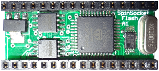
SpinSocket Flash features:
SpinSocket-Flash (30+ PCBs available)
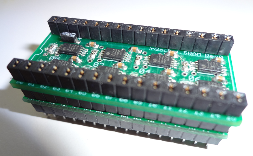
SpinSocket-SRAM (8 PCBs available)
Planned SpinSocket module types (cancelled):
SpinSocket-SD
SpinSocket-ADC/RTC
SpinSocket-TBD
SpinSocket Flash will have up to 4MB of Flash which is byte-at-a-time accessible.
The design allows up to 16MB of byte-at-a-time flash with current SOIC-8 chips.
What's the point of SpinSocket Flash?
1) Allows running Propeller GCC programs, or any other language directly from Flash (Board Type SSF).
2) Boot time is instantaneous (after EEPROM load); no need to wait for SD card access.
3) Code running from Flash/Cache is one of the fastest XMM solutions available.
4) Advantage of the fast byte-wide flash design concept clearly superior and copied by others.
I welcome any Questions, Answers, Feedback, or Suggestions.
Thanks.
--Steve
"Big things in small packages made easy."
SpinSocket Flash features:
- DIP32 package usable with bread-boards
- P9 to P25 Propeller pins free + Serial In/Output P31/P30
- P0 to P8 pins can be used with Flash disabled
- PropPlug compatible
- Stackable and PCB mountable
- 4.5VDC to 10VDC input power
- 4MB onboard Flash +64KB EEPROM
- 80MHz operation
- Decoupling Caps on the bottom
- 4 each 16 pin stackable headers
- $35 each ASP - discount available to forum members
SpinSocket-Flash (30+ PCBs available)
SpinSocket-SRAM (8 PCBs available)
Planned SpinSocket module types (cancelled):
SpinSocket-SD
SpinSocket-ADC/RTC
SpinSocket-TBD
SpinSocket Flash will have up to 4MB of Flash which is byte-at-a-time accessible.
The design allows up to 16MB of byte-at-a-time flash with current SOIC-8 chips.
What's the point of SpinSocket Flash?
1) Allows running Propeller GCC programs, or any other language directly from Flash (Board Type SSF).
2) Boot time is instantaneous (after EEPROM load); no need to wait for SD card access.
3) Code running from Flash/Cache is one of the fastest XMM solutions available.
4) Advantage of the fast byte-wide flash design concept clearly superior and copied by others.
I welcome any Questions, Answers, Feedback, or Suggestions.
Thanks.
--Steve


Comments
Well done.
Bean
Haven't thought it through, but my first thought would be to use DIP-40 so that people with the regular Prop could just drop this in for more power...
@Rayman, I thought about 40 pins and 32 pins (which i may do). I opted against 40 pins mainly because Andrew (WBAconsulting) is doing that. The other reason is that P28-31 are really not necessary and in many ways are just not available to users. A 28 pin part is easier to route with a Propeller and other components.
In the 28 pin version I sacrifice one propeller pin for bringing out VDD for other things. Also, on the SpinSocket-Flash the SPI clock and chip select are not extended to the carrier board. These things are why I'm still considering a 32 pin footprint.
I think the stackable header concept makes it a little different that other things.
This would be like a miniature Propeller Platform...
As for the 40 pin, my M44D40+ module is just the basic Propeller circuit (Prop, Crystal, EEPROM, Programming header) in a DIP 40 format, so if you were providing additional options like flash and onboard regulation, it won't interfere with my target market in most cases. My goal is a simple, breadboardable, ready to run Propeller solution that's about $20. I do have concept drawings for backpacks and a flash/regulator backpack would be easy to make if a crossover between the products was desired.
More products to choose from => more people into the prop
Just have to get the word out!
The one thing I notice is the unusual placement of Vdd. I suppose you cannot place this at pin 1 or pin 13?
With your PropPlug pins, I have a pcb coming which uses 6 pins at the end... 5V,Gnd,-Reset,SI,SO,Px
So I am allowing 5V input (or output) beside the Gnd Pin. I am doing pcb(s) to plug into this. Px is a spare prop pin.
Different boards could be used underneath...
Cluso, the VDD placement is odd I guess. Pin 1 is better because
of short trace length, but the routing for the rest of the board won't work.
I may spend more time with that. We'll see.
Here's the SpinSocket-FTDI board. Features include:
1) User can choose USB power for a connected board
2) Allows the user to disable the FTDI controlled reset
3) Has a reset button
This board would be mounted on top of the SpinSocket-Flash or SD module.
See first post for updated drawings.
I decided to include a 5 pin PropPlug+ header which will make 3.3V available.
http://www.synapse-wireless.com/index.php?mainID=3&subID=3&type=product&prodID=3
An infrared transceiver link would be a nice addition to the list of modules.
At first glance an infrared transceiver will be fastest/easiest to implement.
Most of the 802.15.4 modules I see are bigger than the SpinSocket footprint.
You could probably do it, and I'll sell you some boards if you want to try.
I'll build a few prototypes, but actual production assembly will be farmed out.
I'll hook up with you at UPEW and buy samples. I already have too much to do.
A board with 2 Winbond Flash chips (WSON package up to 16MB) may be worth the effort.
That depends really on how the SpinSocket-Flash works.
David there is no separate Flash on SpinSocket-SD. I don't have room for both.
It's really neat since you got them all on DIP-28 package, which is a REAL space saver, especially with the DIY model airplane (they have to be compact and light).
Another great idea, another great product!
Please help me decide which is better. I wouldn't normally sweat it, but prototypes are a bit expensive and i have several to do this time around.
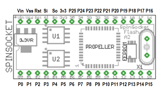
Here images for the DIP32. Notice that there is no special header for prop-plug all pins are on the DIP socket. The prop-plug can be attached to pins 28-31 on the DIP32. The only odd thing about the DIP32 socket is placement of the ground pin is not on 16, but there is some precedent for doing that.
DIP32 Layout example.
Original DIP28 layout example for comparison.
Attached is an updated pinout.
SpinSocket-Flash has data connections on P0..7.
SPI Clock/Chip select are on P26/27 which are not on the socket.
I've added an optional boost regulator to the Flash board to allow running with a AAA battery.
Product should be generally available for sale before UPEW. I'm thinking May 5th is reasonable.
There are 10 PCBs in my office and I have a driver for the flash version now (w25qx2).
Boards can be sold with or without Flash. I do not have SD card boards yet, and I'm not sure the USB module makes sense anymore since the programming pins are on the DIP32 pins.
General availability is dependent on my getting a batch of the stackable headers. I could sell some boards that use small 0.25" square male headers any time. I would prefer to wait for the stackers since they can be plugged into an Augat style socket for bread-boarding.
There are two power management options on the boards:
- LDO regulator with 4.5 VDC input
- Boost regulator for 1.0 to 3.0 VDC input
The first option has been tested. I'll be testing the second option today.Thanks for asking.
One question: if I stack SpinSocket32s - which don't have prop-plug headers - how would I program them?
The 32 pin module has all the prop-plug pins on the socket pins (btw: these modules are not designed for stacking 2 propeller based boards). The 28 pin modules would be fine for stacking propellers since the programmer/3.3v header is not on the socket.
I now have a Propeller running off single a 1.5V battery (recommend 2 batteries for the flash version).
1) Does this have a power regulator on board? If so, what is the minimum VIN?
2) What are the outer dimensions on this?
3) What would be the cost of a spinsocket FLASH if it didn't include: FLASH or stackable headers? How soon could I have 3 configured as described in hand?
There are 2 regulator options: A) Low drop-out 4.5Vin to about 9Vin input provides 3.3V up to about 500ma (@5.0Vin), and
>> 2) What are the outer dimensions on this?
1.65" x 0.74" (0.2" thick with components on both sides not counting crystal or headers).
>> 3) What would be the cost of a spinsocket FLASH if it didn't include: FLASH or stackable headers?
$40 each with 5 or 6MHz crystals and $42 with 6.25 or 6.5MHz crystals. I don't have any more 6MHz crystals, but I could get some in a day or so.
>> How soon could I have 3 configured as described in hand?
Depends on delivery method. I have appointments tomorrow, so earliest I could ship them would be Wednesday. I have 6 un-committed PCBs right now.
This is kind of between a real regulator and a Zener regulator.
The voltage isn't as regulated as a conventional regulator,
however the differential voltage from Vin to VDD can approach
0V. Or really close to 0V.
This circuit is a close relative to an emitter follower.
I use this on my PropStick look alike.
http://www.redrok.com/MOSFET_CPC3703_250V_360mA_4O_Vth-1.6_SOT-89.pdf
http://www.redrok.com/electron.htm#CPC3703
And it comes in a small small SOT-89 package.
Keep the resister values low in resistance so they consume a few mA .
Keep the lead lengths short and the capacitors are required.
Better yet the CPC3703 costs only $0.95us.
Duane
Hi jazzed,
Yeah, it's been a while - family stuff sorta took over!
Ah, I see - I was remembering the stuff you did with Propalyser (?). I guess those pins could be bent out so they could all be accessed if stacked. I like it :-)