

Is there an ERROR in the PS2 breakout document?
 Oldbitcollector (Jeff)
Posts: 8,091
Oldbitcollector (Jeff)
Posts: 8,091
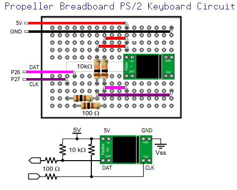
For my recent article, the Propeller Synthesizer I created a simple breadboard illustration to demonstrate how to create the circuit in the simplest terms possible. I took my lead from the PS2 Breadboard board documentation. (A $5. part that Parallax sells.)
Attached are the original illustration which is based on the simple schematic in the official document. It shows both of the pull-up lines attached to the 5v side of the keyboard circuit. Granted they are passing through 10k resistors, so I suspect there would be no issue. Or would there?
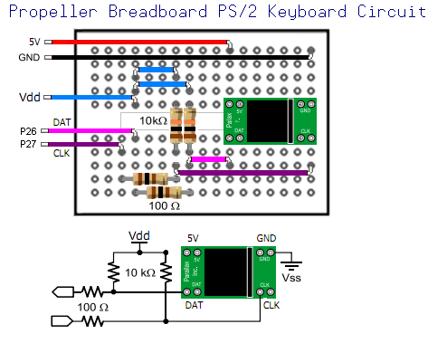
The second illustration, is corrected based on the Demoboard schematic, (not a bad place to fall back to) and the line is removed from the stolen Parallax graphic connecting Vdd to 5v.
Here's the 8 "cog" million dollar question.
a) Is there an error in the documentation? (somehow I doubt it)
b) Did I miss read it? (probable)
c) Can the keyboard be wired this way, as there are nice resistors to protect the pins?
This is more for my edification, so please don't feel I'm nitpicking Parallax. I'm in an instructional capacity, so I want to make sure my own ducks are in a row as much as possible.
Vdd tied to 5v.
Revision based on the demoboard schematic.

Thanks!
OBC
Attached are the original illustration which is based on the simple schematic in the official document. It shows both of the pull-up lines attached to the 5v side of the keyboard circuit. Granted they are passing through 10k resistors, so I suspect there would be no issue. Or would there?
The second illustration, is corrected based on the Demoboard schematic, (not a bad place to fall back to) and the line is removed from the stolen Parallax graphic connecting Vdd to 5v.
Here's the 8 "cog" million dollar question.
a) Is there an error in the documentation? (somehow I doubt it)
b) Did I miss read it? (probable)
c) Can the keyboard be wired this way, as there are nice resistors to protect the pins?
This is more for my edification, so please don't feel I'm nitpicking Parallax. I'm in an instructional capacity, so I want to make sure my own ducks are in a row as much as possible.
Vdd tied to 5v.
Revision based on the demoboard schematic.
Thanks!
OBC

475 x 382 - 52K
473 x 379 - 50K
Comments
As You maybe know --- PS2 Keyboare/Mouse use Open Collector as active signal.
That said in first case You not need protecting resistors If You have pull-up resistors connected to 3.3V.