

Evil Genius Board with Propeller Spin Stamp Microcontroller
 JanosNFS
Posts: 4
JanosNFS
Posts: 4
Hi every1,
I searched for this, but couldn't find anything relating to a "how to" install on the Evil Genius printed circuit board the spin stamp so... here you go
Need:
-PCB from the back of the 123 Robotics Experiments for the Evil Genius book
-Parallax Spin Stamp Microcontroller
-Socket for the chip (the same as for basic stamp 2 you would use 24 legs)
-reset switch
-2 x 10³ capacitors
-2 x 1k Ohm resistor packs (Part# MDP1603 102G DALE 9405)
-2 x resistor sockets (16 legs)
-400 hole bread board
-port sockets (24 inline)
-9v battery holder
Optional:
-on/off switch
-pcb self adhesive legs
You need of course a soldering kit and some electrical wiring, but most of the time the battery holder comes with enough length in wiring(I actually cut them shorter)
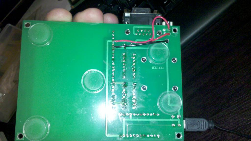
Here are the installed pics and the wiring for the back for the batteries
Vin will be 9v
Vdd will be 5v
p0-p15 will be 3.3v (when it's set for output)
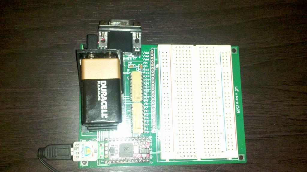

You don't need to install a com port, it won't work with the chip anyway so ignore that.
The positive, red wire from the battery is connected to the first Vin port (#4 from the top) (on the pic the red goes to an on/off switch first and than to the port, but you don't have to install it, just I figured it's easier than taking out the battery every time)
The negative, black wire(ground) is connected to the first Vss(#6 from the top)
This works great for me and hope it will for you too, stay tuned for some project pics that I have done with this already!
Hope this helps")
JanosNFS
I searched for this, but couldn't find anything relating to a "how to" install on the Evil Genius printed circuit board the spin stamp so... here you go
Need:
-PCB from the back of the 123 Robotics Experiments for the Evil Genius book
-Parallax Spin Stamp Microcontroller
-Socket for the chip (the same as for basic stamp 2 you would use 24 legs)
-reset switch
-2 x 10³ capacitors
-2 x 1k Ohm resistor packs (Part# MDP1603 102G DALE 9405)
-2 x resistor sockets (16 legs)
-400 hole bread board
-port sockets (24 inline)
-9v battery holder
Optional:
-on/off switch
-pcb self adhesive legs
You need of course a soldering kit and some electrical wiring, but most of the time the battery holder comes with enough length in wiring(I actually cut them shorter)
Here are the installed pics and the wiring for the back for the batteries
Vin will be 9v
Vdd will be 5v
p0-p15 will be 3.3v (when it's set for output)
You don't need to install a com port, it won't work with the chip anyway so ignore that.
The positive, red wire from the battery is connected to the first Vin port (#4 from the top) (on the pic the red goes to an on/off switch first and than to the port, but you don't have to install it, just I figured it's easier than taking out the battery every time)
The negative, black wire(ground) is connected to the first Vss(#6 from the top)
This works great for me and hope it will for you too, stay tuned for some project pics that I have done with this already!
Hope this helps
JanosNFS
1024 x 575 - 69K

1024 x 575 - 83K