

Logic Problem
 KaosKidd
Posts: 296
KaosKidd
Posts: 296
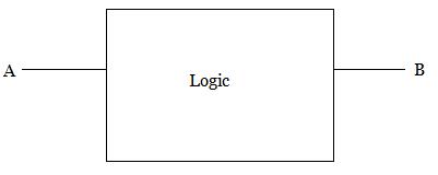
Long time ago, my Digital Electronics teacher had us try to design a bio-directional logic circuit using only logic gates. I don't remember if I had done it of finished it, but here I am, with the same problem and I just can't see it through. The goal is:
input a HIGH on A results in a HIGH on B, input a HIGH on B results in a HIGH on A
input a LOW on A results in a LOW on B, input a LOW on B results in a LOW on A.
Bus contention happens if you connect an output to an output.
This is NOT a tri-state device, it must output HIGH or LOW.
You may use VCC and GROUND as needed.
You may also include a Clock signal between 1 and 50 Hz.
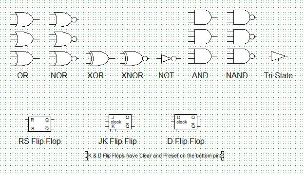
The Image LogicGoal.jpg shows the basic connection schema. The devices permissible are shown in the image LogicGates.jpg.
I use Digital Works (v 3.04.39) as my logic simulator to prove any logic. Can someone PLEASE help me resolve this brain bender before I lose what's left of my hair?
KK
input a HIGH on A results in a HIGH on B, input a HIGH on B results in a HIGH on A
input a LOW on A results in a LOW on B, input a LOW on B results in a LOW on A.
Bus contention happens if you connect an output to an output.
This is NOT a tri-state device, it must output HIGH or LOW.
You may use VCC and GROUND as needed.
You may also include a Clock signal between 1 and 50 Hz.
The Image LogicGoal.jpg shows the basic connection schema. The devices permissible are shown in the image LogicGates.jpg.
I use Digital Works (v 3.04.39) as my logic simulator to prove any logic. Can someone PLEASE help me resolve this brain bender before I lose what's left of my hair?
KK
401 x 160 - 4K
626 x 360 - 94K
Comments
DJ
(just kidding)
Truth table?
What this project is all about is to create a all relay computer (like I've seen in other posts here) in my digital simulator using all relays. I was creating the clock circuit when I discovered this flaw in my relay simulator and I'm at a loss on how to go about getting it right.
I'm not sure I understand Beau.
The end result is B=A and A=B and either can be an input or output. However, if A is input then B is outout, and if B is input the A is output.
Oh, and thanks everyone for the help / suggestions so far. I'm trying the XOR idea now, but no such luck yet.
KK
-Phil
I can't duplicat that in my pure digital simulator
And after spending quite an amount of time in the docs and researching, I think I'm just gonna have to "fudge" the the workings of it...
It's just that I've got this nagging feeling that I'm forgetting something important in all of this...
<sighs> I'll do some more playing...
Take a look at the Bidirectional Isolators, and Translators.
They often use split thresholds and so move into the Analog Domain - this is needed to avoid circular lockup
ie the Logic Zero driven from remote end, Looks like a Logic 0 to Local Digital Loads, but is actually above the back channel threshold
An external drive, pulls the local IP lower than the back channel threshold, and voila, you drive without lockup.
So this is really trinary logic, if you look carefully. : but the digital loads do not look carefully, so they are happy.
Digital Works stops any simulation when any output is not stable. Thus, the ability to make a relay (A=B) and it's underlying project to make a clock circuit with relays, all within a pure digital realm doesn't work in my simulator. I'll have to come up with an alternat method of duplicating the desired effect. I will, it's just going to take some thought on how to design it all.
As it stands now I have several ideas on how to approch the problem from a different POV. I'll post that later one when I get the details of my "new approch" worked out.
Again, thanks everyone,very much so, for the helpful replies and ideas.
KK
It would appear to work in the logical terms, but my simulator doesn't permit it to run.
I still get a bus contention error on the in/output lines when ever there's any device's output line connected. I tried.. But, in theory, this should work... I know it's elaborate, and no one would go to such extremes...