

RcTime Voltage Measurement
 alnajjar1
Posts: 110
alnajjar1
Posts: 110
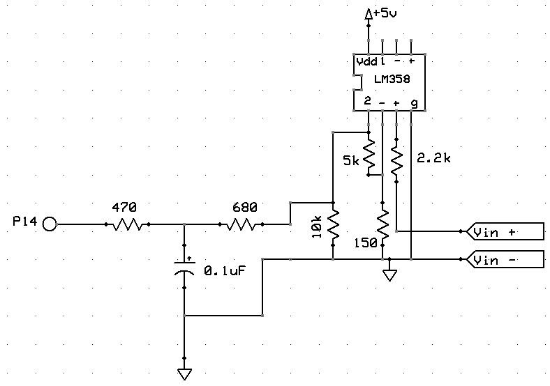
I am using a BS2 to measure DC voltage. My reference was an article EME System (http://www.emesystems.com/BS2rct.htm) to design the circuit. I had to amplify incoming voltage from 0-21 mV to 0 - 3.7V using an LM359 Op Amp, and this works perfectly. The circuit diagram and code are attached.
When I read the RC value, I am getting wild numbers that eventually stabilize to 1 and then nothing happens. I tried changing the delay time in the loop but that didn't do anything.
Can anyone spot what I am doing wrongly? The amplification works and the RcTime circuit and code are very simple. Not sure what is going on! Thanks in advance for any help..
Al
788 x 554 - 44K
bs2
265B
Comments
' {$STAMP BS2}
' {$PBASIC 2.5}

' RCtime stuff
Sig     PIN             14
rcSig   VAR             Word

LOW Sig

again:
  RCTIME Sig, 0, rcSig ' measure RC discharge time
  LOW Sig
  DEBUG CLS, HOME, DEC ? rcSig ' display result
  PAUSE 500
GOTO again
This is the RCTIME code that you should be trying and can you see the differences in Basic Stamp Editor help file and your code above.' RCTIME1.BS2 ' This program shows the standard use of the RCTIME instruction measuring ' an RC charge/discharge time. Use the circuit in the RCTIME description ' (in the manual) with R = 10K pot and C = 0.1 uF. Connect the circuit to ' pin 7 and run the program. Adjust the pot and watch the value shown on ' the Debug screen change. ' {$STAMP BS2} ' {$PBASIC 2.5} RC PIN 7 result VAR Word Main: DO HIGH RC ' charge the cap PAUSE 1 ' for 1 ms RCTIME RC, 1, result ' measure RC discharge time DEBUG HOME, DEC result ' display value PAUSE 50 LOOP ENDJust remember that the RCTIME command isn't the only way for Stamp to measure voltage and they are.1) Analog Digital Converters(ADC) which uses SHIFTIN command (From Stamp Works PDF)
2) Using a 555 Timer IC which uses PULSIN command (From Stamp Works PDF)
Al
Still, The ADC0831 is the best way to go, and you have success with that. Stick with it!