Propeller on a breadboard
I like being able to quickly breadboard an Arduino and would like to do the same for the Propeller -- the support components make this a little harder.
Solarbotics makes a pcb that sits on top of a 28-DIP AVR chip (The Ardweeny: http://www.solarbotics.com/products/kardw/). It uses 0.1" pin headers that you solder to the chip pins. It's really handy and makes for a small, standalone footprint.
So I got the hair-brained idea to do the same for a Propeller. (Maybe someone already did this but hey it's fun) I drafted up a schematic and board design using SMD components (except the xtal) and have some parts on order from Newark and Sparkfun. The initial design is for a built-in FTDI usb-serial adapter. If that doesn't work I guess I'll put a prop plug 4-pin header on it instead. But anyway...
Eagle files: http://code.google.com/p/prop-pack/
I'm entering exciting new electronics fab territory here... Will I be able to use iron+laser printer to make 0.016" traces at home? Is it really possible to do SMT reflow in an electric skillet? Tune in next time...
  Will post updates if I actually pull this off...
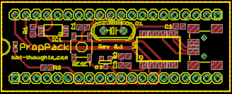
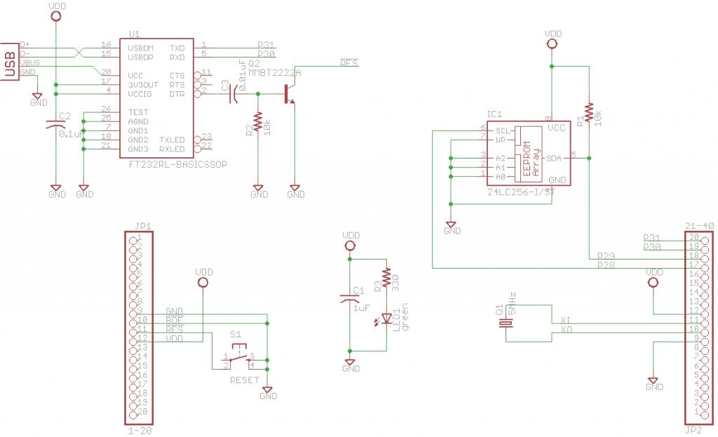
Here's the schematic and board:


LMK if you see any issues with the design...
Thanks,
Michael
Solarbotics makes a pcb that sits on top of a 28-DIP AVR chip (The Ardweeny: http://www.solarbotics.com/products/kardw/). It uses 0.1" pin headers that you solder to the chip pins. It's really handy and makes for a small, standalone footprint.
So I got the hair-brained idea to do the same for a Propeller. (Maybe someone already did this but hey it's fun) I drafted up a schematic and board design using SMD components (except the xtal) and have some parts on order from Newark and Sparkfun. The initial design is for a built-in FTDI usb-serial adapter. If that doesn't work I guess I'll put a prop plug 4-pin header on it instead. But anyway...
Eagle files: http://code.google.com/p/prop-pack/
I'm entering exciting new electronics fab territory here...
Here's the schematic and board:


LMK if you see any issues with the design...
Thanks,
Michael


Comments
Take a peek on page 6 of this thread. Such a coinidence, I just posted there and then saw your thread. It applies to diy breadboards for the propeller proto board.
http://forums.parallax.com/showthread.php?124495-Fill-the-Big-Brain
Bruce
It would be great if you could put a solder-tail socket on the board to accept plugging in a DIP40 propeller. That might mean moving the crystal and reset button. The crystal would easily fit in the open space of the socket or the center rail of the socket could simply be snipped. The reset button might be optional or put on an extended pin 1 side PCB area - a 2 pin header could serve the same purpose with the same size PCB.
Good luck with this.
Looking pretty good. It may be worth putting in two bypass capacitors. 0.1uF. Put them as close as possible to the propeller power supply pins.
Ya, Dr_A is right about those by-pass caps ... add one for the FTDI chip if you can. While you're at it, may as well add pads for a 10uf 10V tantalum cap for extra by-pass to make the over-clocker's happy. Since you have little room on the top side, put the caps on the bottom.
I've been looking at the FTDI stuff, and have decided to use board power for the VDDIO pin instead of 3V3OUT. That way the chip won't try to power your entire target breadboard when the target power is turned off. If you follow this method, you should add the board detect voltage divider for RESETn. Without the resistors the device may not auto-identify when connected. Look at the FT232RL spec.
what software are you using to layout your PCB design?
My main goals for this project were low price and a standalone Propeller that's easy breadboarded so I can do more Propeller-based projects.
@jazzed: thanks for the info on the FTDI / power issue. WIll check it out.
Regarding the solder tail socket -- I think I understand what you're saying. Will give that some thought. My plan was to use 20x1 0.1" pin headers pointing down so the board can sit on top of a D40, and then solder the pin header to the prop's pins, similar to the Ardweeny (which costs $10):
@MagIO2: Versus the propstick. Difference is primarily price. The stick is $80 (eek!!!) What I'm working on will be considerably less.
At this very initial stage, the PCB is around $5 / board (far less if I can fab it at home), all the components are around $15 plus $8 for the prop. If I dropped the FTDI chip and used a 4-pin prop plug header that'd be $6 less. I may yet go that route.
Of course there's shipping and handling fees but in addition to ordering several at once, maybe I can get some folks in my local robot clubs to go in with me to defray some of those costs, too.
Anyway thanks again for the comments, I really appreciate it!
EDIT: I'm using Eagle CAD for schematic and pcb layout.
I ditched the FTDI chip and added a Prop Plug header and Sparkfun FTDI breakout board header. I figure if anyone wanted to make this board or go in with me on one, they'd probably have (or could justify getting) one of those two programmers. Losing the FTDI, etc. makes the component cost cheaper and the board less crowded.
Now it looks next as my one.
CPUModule
I think the FTDI chip adds value; it is expensive, but worth the trouble. Since you're leaving it out, I think I'll make a board that has it
Only if you place zero value on your time! <wink>
I like your 'backpack' idea. I'll be keeping an eye on this.
This would make replacing a fried chip easier and decrease the chance of damaging the prop's own pins
@JonnyMac: good point
@Sapieha: nice work on the pcbs! I may have to order one from ya
@jazzed: FTDI -- now you have me rethinking. It's really nice on the mbed to just plug in the USB and go. Maybe I'll make a version with FTDI later... or just wait for you to make yours. I'll reserve one now.
@agimuhing: that's a really good idea. For an $8 chip it's probably a good idea to be able to replace it easily. Plus, you can transfer the chip from breadboard to a custom PCB that includes the support components and other circuitry... I'll see if I can source 20-pin stackable headers...
I found last night that making 16 mil traces is actually trivially easy. I made a board for my Wii cam homebrew LIDAR using 0805 sized passives etc and used my brand new "Reflow Skillet" which was also surprisingly easy. I've finally entered the 90's.
Well, I fabbed up the first prototype. Transfer and etch of the 16 mil traces was no problem at all. And the TSSOP chip worked. But I officially hate TSSOP and will switch to SOIC on future versions.
I stupidly put the EEPROM on upside down and fried it so now I have to order another.
I agree the Ardweeny looks hacked. Mine won't win any aesthetics contests either.
Parts cost around $2.50 per board (ordering from Newark) + shipping. Haven't priced Digi-key (where you can get free shipping). Board, around $4.50 plus $10 per run for S&H thru BatchPCB. The board is still single layer so a home hobbyist could do their own and save some bucks.
I designed an all through-hole version which would be cheaper for most folks since they have a stockpile like me. And it would be more accessible to a home hobbyist. Maybe I should go that route.
I looked and looked for 20-pin stackable headers. No dice. If you find some, let me know.
Once I get my replacement EEPROM I get to actually verify that the thing works.
More later...
I am using Samtec headers for the module that have a standard 0.025" square post on top, but a smaller 0.018 round pin on the bottom so that it closely replicates a IC pin better for PCB sockets. The Samtec part number is TSW-120-26-G-S. They are hard to find because the drawing is a "TSW Series" drawing and since only lead style "26" has this custom pin, there is just a note calling out "Except: Style 26
(0,46) .018 DIA Tail". The female headers are typical. A "stacking" female header is simply a female header with a very long tail length. For example, SSW-120-04-G-S, is a female header with 0.584" long leads. With a board thickness of 0.062", you will have a .522" long lead to plug into a breadboard or another female header to continue the stack.
Only, I use Ultiboard. How do I convert the ewprj file into a sch?
In the same way that you can build an Arduino on a breadboard (http://www.arduino.cc/en/Main/StandaloneAssembly), you can also build a Propeller system on a breadboard. A while ago, I downloaded a layout from www.topprop.net which showed a breadboarded Prop system. The domain is not registered now, and I cannot find to where it has been moved (if at all), but I did use it in a simple project of building a homebrew Propeller Education Kit. I uploaded my document to my server (files.granzeier.com/Downloads/A Simple Propeller Breadboard-Perfboard Layout - Homebrew PEK.doc) so that you can take a look at it. If you use a PropPlug, you can eliminate the MAX-232 and associated circuitry and replace them with a simple 4-pin male header. Put this onto a double- or triple-wide breadboard, and you can add lots of additional circuitry.
If there are any troubles with copyright, or any other rights, and the original authors request it, I will remove it from my server. Until then, I hope this helps.