

Trying to debug apparent hardware issue when intefacing microSD adapter to propeller
 Dan E
Posts: 61
Dan E
Posts: 61
I have been trying for some time now to use code that has been proven to work others, but I have not been able to get it to work for me. The object I am trying to use plays WAV files from an SD card. It was suggested to me to go back and analyze the hardware connections.
I have been able to succesfully use objects for other applications, this tells me the prop is wired fine, but I am unsure as to whether there might be something I am forgetting or unaware of when interfacing the microSD apdapter with the prop.
Just to double check, I completely took everything apart, and rebuilt trying to arrange things in the same way as the propeller education kit schematic. Again, my other objects ran fine. So I still think maybe I might be connecting the microSD adapter incorrectly.
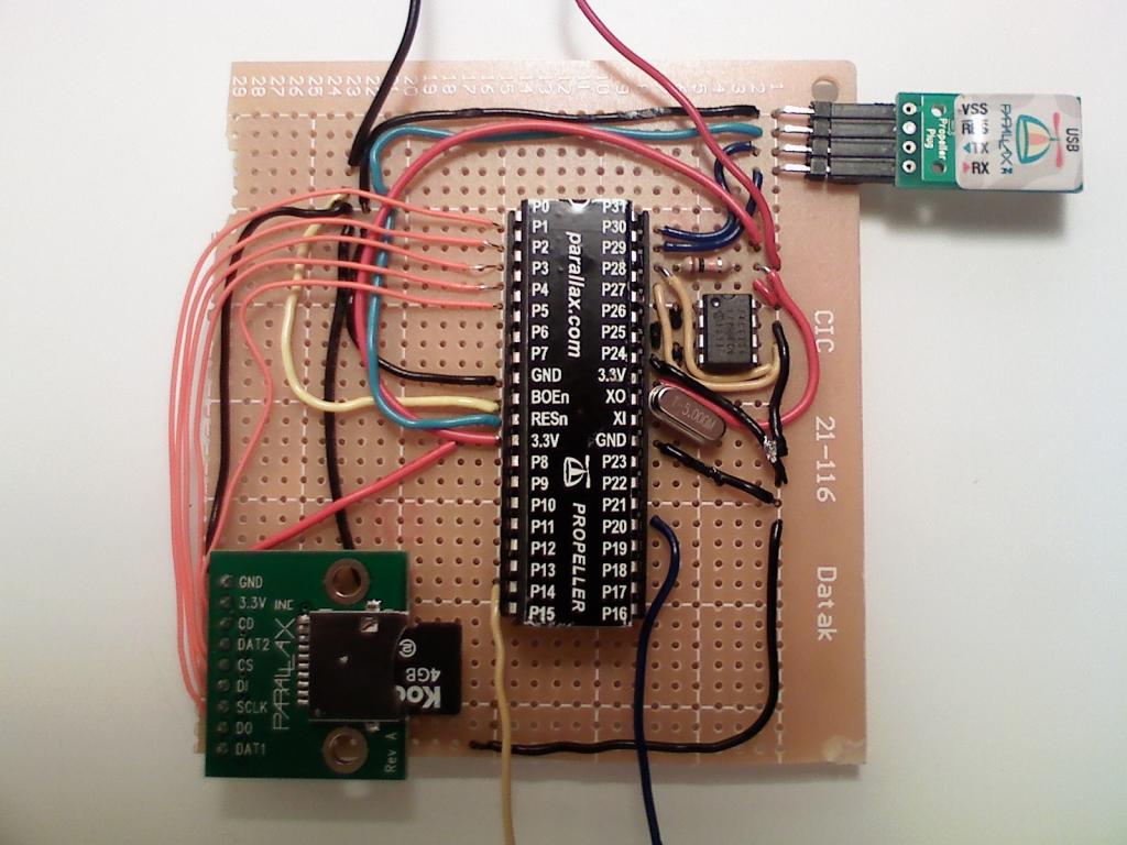
I followed the diagram from the datasheet on the store webpage. Atttached is a clear picture of my connections, some wiring around the eeprom is a little busy, but it clearly shows how am I connecting to the microSD adapter.

Here is the link to the datasheet
http://www.parallax.com/Portals/0/Downloads/docs/prod/acc/32312-microSDCardAdapter-v1.0.pdf
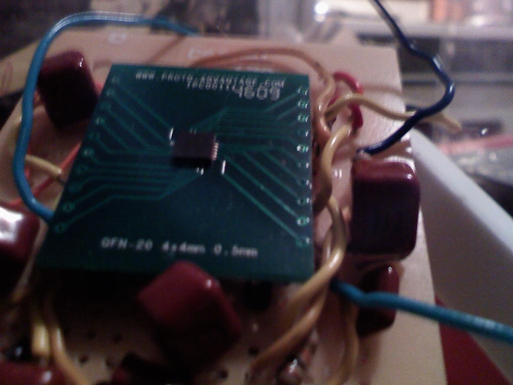
I used a MAX4411ETP stereo amplifier to connect to my speaker, that I've tested just by hooking it up to my ipod and it worked fine, just soft due to the mismatch in impedance from the ipod to my speakers, This wiring is also a little busy due to the lack of space a had on that thin board, but it works properly.

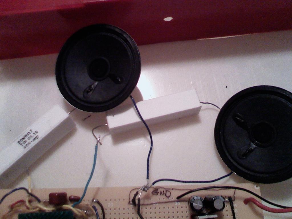
The only other variable I can think of is maybe theres a larger impedance or signal mismatch between the output, the stereo amplfier chip, and my speakers. I have two 8 ohm speakers, so I placed an 8 ohm resistor in series with each of them.

Maybe there is something here that someones sees that is obvious to them, but not to me. I would appreciate any suggestions.
Attached is the code I used, with pin selections.
Thanks,
Dan
I have been able to succesfully use objects for other applications, this tells me the prop is wired fine, but I am unsure as to whether there might be something I am forgetting or unaware of when interfacing the microSD apdapter with the prop.
Just to double check, I completely took everything apart, and rebuilt trying to arrange things in the same way as the propeller education kit schematic. Again, my other objects ran fine. So I still think maybe I might be connecting the microSD adapter incorrectly.
I followed the diagram from the datasheet on the store webpage. Atttached is a clear picture of my connections, some wiring around the eeprom is a little busy, but it clearly shows how am I connecting to the microSD adapter.
Here is the link to the datasheet
http://www.parallax.com/Portals/0/Downloads/docs/prod/acc/32312-microSDCardAdapter-v1.0.pdf
I used a MAX4411ETP stereo amplifier to connect to my speaker, that I've tested just by hooking it up to my ipod and it worked fine, just soft due to the mismatch in impedance from the ipod to my speakers, This wiring is also a little busy due to the lack of space a had on that thin board, but it works properly.
The only other variable I can think of is maybe theres a larger impedance or signal mismatch between the output, the stereo amplfier chip, and my speakers. I have two 8 ohm speakers, so I placed an 8 ohm resistor in series with each of them.
Maybe there is something here that someones sees that is obvious to them, but not to me. I would appreciate any suggestions.
Attached is the code I used, with pin selections.
Thanks,
Dan
1024 x 768 - 95K
1024 x 768 - 67K
1024 x 768 - 81K
Comments
On Yours First PCB I can't see any decoupling capacitor --- That not good.
But I do not have decoupling capacitors coming from the SD adapter. Where do they attach to the SD card? Do they change its operation?
It looks like I forget to attach the object files I used in my first post, here they are.
!WAV Player - Archive [Date 2011.01.23 Time 02.38].zip
I noticed there are special circuits associated with the objects I used from the object exchange for this application. I think this may also be what I am lacking. Since these objects are used for multiple applications, I am confused about the correct pin attachments.
For the DS1307_RTCEngine object, do the DS1307 SDA and SCL pins refer to pins 28 and 29 on the prop? Also are the Data and Clock pins assigned to the same pins that will be used with the SD card?
For the PCM2.1_DACEngine object, 100 ohm resistors are used with the ouput signals, rather than the 10K resistors that are used in the Demo Board schematic. Could this cause the soft distortion I heard?
The Demo Board schematic is in the link below.
http://www.parallax.com/Portals/0/Downloads/docs/prod/prop/PropellerDemoBd-RevG-Schem.pdf
Lastly, in the SD3.01_FATEngine there are several circuits, I asume each is for one of the many applications the object does, but none of the pin selections correspond to the microSD adapter pin selections from the datasheet (link is above in my first post), so I am not sure which is the approriate one to use.
If anyone has used the schematics in any of these objects, I would appreciate some help deciphering.
Thanks for the feedback,
Dan