

frustrated with transistor circuit
 Britannicus
Posts: 98
Britannicus
Posts: 98
I'm doing something terribly wrong and being a total dummy with my BS2 circuit.
I have a 0.5 amp 6v motor (ultimately I want to use 2 in skid steering a robot). It won't run direct from my Stamp - not enough current.
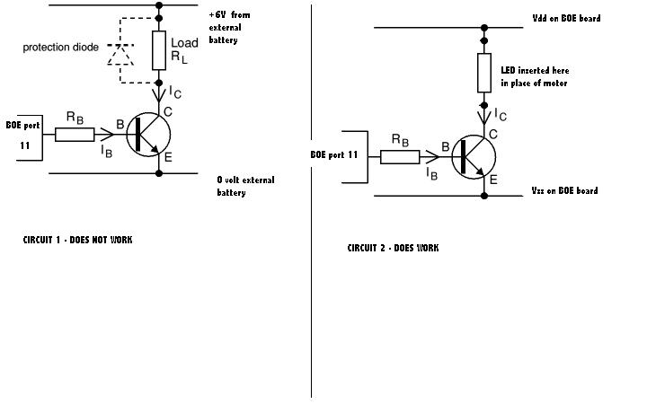
What I want to do is to switch an NPN transistor and figured the diagram attached should do it - looked simple enough.
I hooked up a more powerful 6V battery and in a straight connection to the motor it then ran fine.
next
I then created a pulse on / off from a BOE board with my stamp, and proved it worked with an LED linked from the BOE Vdd to Vss being switched to an fro with the output from port 11 switching on the circuit from vdd to vss connecting the LED and flashing it successfully .
next -
1/ I connected the motor terminal to the +ve terminal along with the parallel diode
2/ connected the other terminal of the motor to the collector of the transistor I'd used earlier
3/ left the base connected to the BOE output terminal (no connections to Vdd or Vss now)
4/ connected the emmittor to the -ve terminal of the external battery.
I've used a transistor rated at 1 amp, and the base signal is over the threshold (or circuit 1 won't work)
I know this is wrong somehow, but just can't work out how - should there be a connection to the vdd somewhere ?? - if so how is that rigged up - I'm really stumped.
Hope you can enlighten me from being such a dummy !
I have a 0.5 amp 6v motor (ultimately I want to use 2 in skid steering a robot). It won't run direct from my Stamp - not enough current.
What I want to do is to switch an NPN transistor and figured the diagram attached should do it - looked simple enough.
I hooked up a more powerful 6V battery and in a straight connection to the motor it then ran fine.
next
I then created a pulse on / off from a BOE board with my stamp, and proved it worked with an LED linked from the BOE Vdd to Vss being switched to an fro with the output from port 11 switching on the circuit from vdd to vss connecting the LED and flashing it successfully .
next -
1/ I connected the motor terminal to the +ve terminal along with the parallel diode
2/ connected the other terminal of the motor to the collector of the transistor I'd used earlier
3/ left the base connected to the BOE output terminal (no connections to Vdd or Vss now)
4/ connected the emmittor to the -ve terminal of the external battery.
I've used a transistor rated at 1 amp, and the base signal is over the threshold (or circuit 1 won't work)
I know this is wrong somehow, but just can't work out how - should there be a connection to the vdd somewhere ?? - if so how is that rigged up - I'm really stumped.
Hope you can enlighten me from being such a dummy !
bmp

949K
720 x 450 - 23K
Comments
The diode is not optional. When the pulse stops, the collapsing magnetic field in the motor windings will produce a voltage spike that may destroy or damage the transistor. The diode dissipates the voltage spike.
-Tomato
After a bit of jiggery-pokery I've tried the solution with the micro relay - tried the following from maplins in the end - it's specified at 6V for switch, bu tseems to work just fine on the 5V from the BOE Vdd although the pin spacings make it a bit of a pain to fit on the breadboard.
http://www.maplin.co.uk/2a-6v-spdt-ultra-miniature-relay-218089.
The Maplin Ref is N99CZ
-Tomato