

Options for Storing data on shutdown
 EmptyBit
Posts: 72
EmptyBit
Posts: 72
I have been studying power sustaining circuits here and around the web to store a few bytes of data to my SD card after the power switch has been turned off. Of the dozens of ways to do this, not many point at the propeller with proven circuits, component values and tested time frames.
I only need to save 5 bytes in a text file, yet Mike Green states in one thread, the SD object writes in 512 byte blocks and could take a second or two to complete?
Options:
Phil Pilgrims mosfet latching circuit would work fine. The P channel mosfet needs to be app load specific. Maybe 1amp would do just for the prop without any external loads. Nice it is not time dependent.
http://forums.parallax.com/showthread.php?104658-Another-power-on-off-brainstorm&p=735032&viewfull=1#post735032
Everything else becomes a race between how much data needs stored over what "capacitance set" time frame before the lights go out for good.
High tech 8pin watchdog supervisory IC's. Fancy comparators waiting for voltage drops, for what it is worth.
Brownout detectors like the TC54. A comparator in a 3 pin TO-92 package.
http://www.parallax.com/Store/Components/IntegratedCircuits/VoltageRegulator/tabid/615/CategoryID/80/List/0/SortField/0/Level/a/ProductID/387/Default.aspx
These are active devices that trigger an input and the resulting action to take. I have managed to write the code to save and restore my data. I just need a bit of component value advice from proven tested hardware that doesn't compromise my hardware.
I did find one passive circuit that should handle this as well. I will be using the prop proto boards and they have a 1000uF cap already there for servo use. I do have a couple .47F Supercaps, although I read there can be complications with these charging from a stand still without series resisters and directing diodes.
I was surprized to find this method of saving data on shutdown commonly discussed on the web, but so vague with no follow up posts put out there for others to absorb the resolution with circuits to wrap it up.
Short of by guess and by gosh calculations, doing tests with my old scope or writing a timing routine to see how long this write takes, I thought I'd try here first.
And maybe suggest a programmable Boen threshold on the Prop II, like many PIC chips have that has been successfully used for this exact purpose.
$0
847 x 888 - 20K
Comments
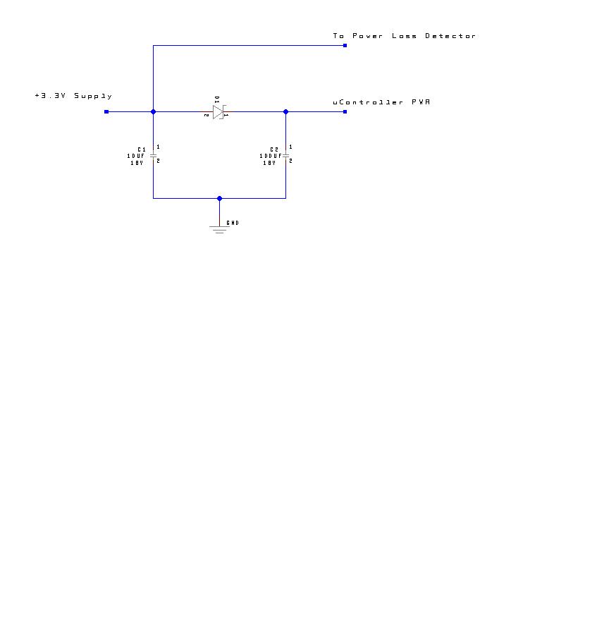
In parallel with the 1000uF the 1000uF will provide current for short term transients as it has a much lower internal resistance. And the 0.47F cap will provide power for many seconds.
Rule of thumb formula - 1 Farad capacitor discharging at 1 amp drops 1 volt per second. 0.47F is a half a farad so will discharge 2 volts per second when drawing an amp. Your prop would be unlucky to be drawing an amp. Maybe the sd card draws 200mA? So you ought to have a few seconds. And you could parallel up a few supercaps if needed.
Phil Pilgrim did some real world current tests in this thread. Although no tests under SD writing.
http://forums.parallax.com/showthread.php?109372-Propeller-Current-Consumption-Oddities-and-a-Conclusion
I am surprised that the SD could draw 200mA. Adding this in with Paul Baker's coulumbs/second calculation would need on order of x10-x15 compensation @ 20ma with 22uF for 660uS?
http://forums.parallax.com/showthread.php?99391-shutdown-procedure-with-i2c-memory&p=693250&viewfull=1#post693250
So a worst case scenario might be 250mA. By my calculations to use the passive or external comparator trigger cap supported, with .6volt headroom of sustained power above 2.7v with a 1/4amp load, I may need .66F to get 1.5 seconds.
Maybe Phil's latching circuit is wiser.
$0
I am using a (quite physically small) 1F Super Cap and a 1000µF. When the propeller detects power outage, it goes into a power save mode running at 20kHz and only 1 cog, and has the capability to shut down a lot of hardware. In this mode, the entire system draws about 8-10mA, but even with all this, it only lasts for 30 seconds. This is because the cap is only charged at 3.3V, and around 2.6-2.7V the propeller cuts out.
With the high internal resistance (my capacitor is 30-ohms as well), that automatically drops 0.3V at 10mA. So that's only allows for a 0.3-0.4V drop before the propeller dies.
This is the first time I've done the math, but it works out perfectly. 3.3V - 0.3V (cap resistance drop) = 3V. Dropout is 2.6-2.7V so 3V - 2.7V = 0.3V change. 0.3V / 0.01mA = 30 seconds @ 1F (1V drop per amp per second).
You could double your run time by charging the capacitor at, and running the propeller at 3.6V. Or charge it at 5V and regulate it down to 3.3V, but then you loose a lot in the regulator, so your run time will be significantly based on the quiescent current draw of the regulator.
At 200mA, you get 6V drop across the 30-ohm capacitor, so...uh...yeah, I don't think that will work. With 10x 30-ohm 1F capacitors, you might be able to get it to run for a second or so, but probably not, because of transients.
Hopefully that had something to do with the original question...
If You need both RTC and FRAM why not use that one.
RAMTRON FM31L27x series board with RTC/32 KBytes FRAM
If anyone wants to view the intent of my project, here is a thread I posted a week ago. I would only be opening one file name and only planned storing the new values back to it, once per day when the switch goes off.
http://forums.parallax.com/showthread.php?128342-Save_me-Restore_me-on-my-uSD
I am not running on batteries, so I don't have that to worry about. For the most part, I was using the uSD card for wav files anyways, so it was a matter of convenience. I was hoping to stay as minimalistic as possible without adding more components.
The stock eeprom is already there, so yes, that is an option for data storage. As a guestimate, there may be up to say 300 writes per year. Not really all that much wear to the eeprom or SD in 10 years.
I could rewrite the Save_me/Restore_me code to save to the eeprom rather than the SD card. As soon as I come up with similar methods to do that. Or just buck up and use the latching mosfet circuit to be done with it. Either way, perfectly functional is fair enough.
$0
Yup, I will check that out tonight. Adding another driver was the other concern. I am very close to the memory max as it is. Although, at one time, I did edit a version of FSRW with the write function commented out to minimize its footprint. I could go back to that version if not writing to the SD anymore.
$0
Yes, I put the data contiguous so it was easy to array in and out. I left them as longs how Ariba did when he helped optimize the graphics buffering for me. So, I am saving longs to bytes in the settings array, as one ASCII byte is stored for each.
I have started working with Kye's RomEngine. It only consumes 128 longs compared to 479 for the Memory_Store lightweight. Although from what I see, the romengine overwrites every time and the MemStore object only overwrites what has changed. I may be able to add that feature into my Save_me section as if it was worth worrying about wear on the eeprom at well under 400 writes/year.
For debugging R&D I have been using the prop demo board, which lacks the pull-up on SCL line, causing failure of the romengine demo. I see the Proto boards have both eeprom pull-ups. I had to don my opti-visor to see of it was possible to add a SCL pull-up to the Demo Board, but YIKES, that ain't a lot of room to work in! Too much risk there.
Meanwhile, I’m back to my consternation and procrastination. It appears that I cannot run Kye’s eeprom driver on the Demo Board as built. I need to run some demo’s to learn how the driver works and incorporate it into my Save_me/Restore_me methods.
I guess it is time to get a proto board set up for the real deal anyways. That would get me past this latest challenge and moving forward.
This code below has not been tested, but posted here to see if I am on the right track.
$0
''*************************************** ''* Voiced Counter & Display * ''* * ''* * ''* Copyright (c) 12/27/2010 * ''* See end of file for terms of use. * ''*************************************** CON _clkmode = xtal1 + pll16x _xinfreq = 5_000_000 _stack = ($2800 + 100) >> 2 'accomodate display memory and stack x_tiles = 16 y_tiles = 10 paramcount = 14 bitmap_base = $5000 display_base = $5000 lines = 5 thickness = 2 bufferlen = 400 VAR long mousex, mousey long tv_status '0/1/2 = off/visible/invisible read-only long tv_enable '0/? = off/on write-only long tv_pins '%ppmmm = pins write-only long tv_mode '%ccinp = chroma,interlace,ntsc/pal,swap write-only long tv_screen 'pointer to screen (words) write-only long tv_colors 'pointer to colors (longs) write-only long tv_hc 'horizontal cells write-only long tv_vc 'vertical cells write-only long tv_hx 'horizontal cell expansion write-only long tv_vx 'vertical cell expansion write-only long tv_ho 'horizontal offset write-only long tv_vo 'vertical offset write-only long tv_broadcast 'broadcast frequency (Hz) write-only long tv_auralcog 'aural fm cog write-only word screen[x_tiles * y_tiles] long old1, old2, old3, old4 long D1, D2, D3, D4, setcolor byte settings[5] long f_ext byte f_name1 byte f_name2[2] byte f_name_ext[6] byte buff[bufferlen] OBJ wpl : "WavePlayerSdAccess" tv : "tv" gr : "graphics" mouse : "mouse" rom :"I2C_ROMEngine" PUB start | i, dx, dy, numx wpl.start(0, 10, 11, @buff, bufferLen) 'Start I2C driver rom.ROMEngineStart(_clockDataPin, _clockClockPin, -1) Restore_me 'Fetch settings off eeprom instead of SD card 'Set up display longmove(@tv_status, @tvparams, paramcount) tv_screen := @screen tv_colors := @colors tv.start(@tv_status) 'init colors 'setcolor := 1 setcolor := settings[4]-48 'convert setcolor ASCII chr. back to dec colorswap(setcolor) 'init tile screen repeat dx from 0 to tv_hc - 1 repeat dy from 0 to tv_vc - 1 screen[dy * tv_hc + dx] := display_base >> 6 + dy + dx * tv_vc 'start and setup graphics gr.start gr.setup(16, 10, 128, 80, bitmap_base) '(x_tiles, y_tiles, x_origin, y_origin, base_ptr) 'start mouse mouse.start(24, 25) 'D1 := D2 := D3 := D4 := "0" longmove(@old1, @D1, 4) 'set font gr.textmode(10,16,6,5) 'textmode(x_scale, y_scale, spacing, justification) 'my counter set at (10,16,6,5) 'D1 := D2 := D3 :=D4 :="9" repeat 'clear only changed area gr.colorwidth(0,8) 'text color and width 0,8 dx := 70 if old2<>D2 dx += 65 if old3<>D3 dx += 65 if old3<>D3 dx += 65 gr.box(135-dx,-72, dx, 145) 'draw digits gr.colorwidth(2,8) 'text color and width 2, 8 gr.text(-95,0,@D4) gr.text(-30,0,@D3) gr.text(35,0,@D2) gr.text(100,0,@D1) longmove(@old1, @D1, 4) 'copy new digits to old repeat until mouse.button(0) 'Left Mouse, would be count up 1 'Not enough mouse buttons for debugging in whole if mouse.button(1) 'Count will be M'sw input, repeat while mouse.button(1) 'Clear and Voice counter will be P.button setcolor := setcolor+1 ' if setcolor > 8 'save will be auto at every powerdown setcolor := 1 colorswap(setcolor) if mouse.button(2) 'Mouse wheel click for now Save_me 'Save settings to SD card repeat while mouse.button(0) Pri colorswap(NUMX) tv_colors := @colors[setcolor-1] return Pri Save_me |i 'eventually triggered via a power down watchdog? repeat i from 0 to 3 'Store array settings to the SD card bytemove(@settings[i],@D1[i],1) 'Save D1-D4 settings[4]:= setcolor+48 'convert setcolor to an ascii chr. rom.writeByte(@settings, settings) { repeat i from 0 to 3 'Store array settings to the SD card bytemove(@settings[i],@D1[i],1) 'Save D1-D4 settings[4]:= setcolor+48 'convert setcolor to an ascii chr. wpl.popen(string("data.txt"),"w") 'Open the file name Data.txt wpl.pwrite(@settings, 5) 'write settings to it wpl.pclose } return Pri Restore_me|i 'Nothing written here to support read from eeprom yet...... {wpl.popen(string("data.txt"),"r") 'open stored data array settings to the SD card wpl.pread(@settings, 5) 'read data into settings array wpl.pclose 'close data file repeat i from 0 to 4 'extract settings to D1-4 and setcolor ASCII chr. bytemove(@D1[i],@settings[i],1)} return DAT tvparams long 0 'status long 1 'enable long %001_0101 'pins long %0000 'mode long 0 'screen long 0 'colors long x_tiles 'hc long y_tiles 'vc long 10 'hx long 1 'vx long 0 'ho long 0 'vo long 0 'broadcast long 0 'auralcog ' Foreground Background color colors long $00_1B_00_07 '1B=Blue 07=White long $00_07_00_1B '07=White 1B=Blue long $00_8E_00_1B '8E=Yellow 1B=Blue long $00_1B_00_8E '8E=Blue 1B=Yellow long $00_8E_00_02 '8E=Yellow 02=Black long $00_02_00_8E '02=Black 8E=Yellow long $00_07_00_02 '07=White 02=Black long $00_02_00_07 '02=Black 07=WhiteEven though your data are in long form everything is bytes to an EEPROM.
I had read that the eeprom and ram were of the same addressing format. Therefore, I was wishful thinking to just write these bytes directly to the @settings array in the eeprom from the @settings in ram? Am I actually writing a whole page of 32 bytes to save 5 of my own? I was thinking is was more selective than that.
$0
As a refresher from above, the final stage of this project is to save data at detected power down to the protoboard eeprom with residual stored voltage before brown out. The first prototype of my project is near ready to stuff in an enclosure after this is resolved. I have the new code capable of storing to the eeprom as suggested. Although I was doing that with a mouse click, the data did persist in the eeprom after power cycling.
Then I have placed a supercap in parallel with the 1000uF servo capacitor as suggested. When power drops out at the DC supply connector, 5vdc stored in the caps back-feeds through the regulators all the way to the supply connector. The expectation was that this would only feed the 5v back to the 3.3v regulator input. Part of this plan was to use the servo power supply jumper(X5) to detect main power loss at the Vin pin dropped out on Pin 8. Vin ends up with leached capacitor voltage as well.
At this point I am not sure if there is a way to isolate the main supply without cutting traces and tapping in diodes. I was also leaning toward using a 12v supply with the caveat that it could be an issue with the regulator if at high current loads. 95% of the time, it will be idling in a loop just the basic on-board components, so very little loads. Detecting the 12v at Pin 8 will be interfaced with a 100k resistor as I read to be acceptable. I was thinking a 3v zener to ground would be wise too.
The next question would be detecting the event. Should this be done in a new cog/separate OBJ as a constant watchdog on Pin 8? Given the short unknown time to save, is it realistic to put it in the main repeat loop? The main loop is monitoring external events anyways, but could be caught in process and not notice power loss until it returned to the main loop. uS do count here....
I'll need to place an order for parts either way, Ill put suggestions on the shopping list.
$0
Also, a slightly better idea (in my opinion) than the 3V zener, would be a voltage divider. So, if you keep the 100K resistor, and add a 47K to ground, the threshold on the input will trigger when the input is below 5.16V (you can change the value to change the threshold). With the zener, the input voltage would have to drop to below 1.65V otherwise. But it may be too late at that point (depending on the power-loss curve).
I did something similar with the supercap thing (EDIT: so it appears I already mentioned this above), to save info as it lost power, internal capacitor resistance and power current can make massive differences on how long you have (and it's all exponential or logarithmic, depending on which way you're measuring it). What kind of supercap are you using?
I sincerely appreciate your time to respond again.
I suspect that as Mike Green points out above that 20mS should be used as the base time for storing my block of 5 bytes. My intentions are to multiply that envelope for a margin of safety. I have a .047F in the circuit now. I had a .47F but misplaced the bugger somewhere. This first attempt was just temporary to see what the voltage decay looked like and what other issues I could expect. Back feeding being one of my concerns. I didn't want to start damaging regulators. If the back feed voltage does not compromise the regulators, this would still be usable if there is enough left over to drive the prop through the eeprom saving routine. I am using the Propeller Eeprom.spin.
I did not get a chance to see what the current draw actually amounted to, so no frame of reference to estimate capacitance time constant needed yet.
I envisioned the input on Pin 8 would just watch for loss of the incoming supply at the 3v zener to drop out. I expected that to happen rapidly, but not so.
I then wondered if part of the problem is that the onboard switch is maintaining the feedback. If I remove the switch and switch the power through my external DPST rocker switch, then no power would be leached back from the regulators at Pin 8. I still suspect that voltage will bleed back through the regulators without directing diodes to block it. My worry there is that the .6v drop across several directing diodes will defeat the whole purpose of the caps storage.
$0
Well under the initial 250mA estimate discussed earlier. So the rule of thumb would conclude with 1F supercap with 100mA draw, should net me about 10 seconds/volt drop. .47F about 5 seconds/volt. .047F roughly 500mS/volt or 5x more time than it should take to save up to 128bytes. Knowing I only have .6v from start to finish writing, still should net me 250mS to complete the save task. In a perfect world?
Once I can isolate the cap voltage back feeding, it will be time to test that theory.
$0
Because, with a 0.047F cap you need a capacitor that has 8.8 ohms (ESR) or less to power your device at 65mA for 20mS (in a perfect world).
A lot of the supercaps I've seen (especially the cheaper ones) are usually 30 ohms or so. Which would mean you would get 0 (literally) time. When the power draw switches to the capacitor, there is already too much current to supply 2.7V.
Data Sheet
The spec as I read it states max of 40ohms @ 1khz. Yes, I have read 30ohms is standard ESR so I certainly overlooked that one.
Well, all I can confirm is that after charging to 4.85vdc, pulling the PS plug the little proto LED stays lit for nearly 2 seconds or more. Where 3.6-2.7 fits into that time frame, I have yet to determine.
Between other life obligations, I have been doing some research on backup system for both battery and supercap storage sources. Many show .3v directing diodes and recommend adjustable regulators to compensate for the diode voltage drops.
One backup idea not including regulators
If that is the case, would it be wiser to go with Phil's mosfet latching circuit which the prop drops out after the save is complete? I'm just think solding part in is easier that ripping parts off the board in trade to compensate for a reserve power system.
Doom, despair and indecisive agony.... so goes the consternation of being an efficient tightwad verses just efficient. LOL!
I really want to do this right so these things can multiply like rabbits within our organization. Not likely we plan to sell them, but I don't want to design in a flaw that needs constant attention.
$0
In my designs, I was able to get the 1F capacitor to work for us. But the Propeller had to detect the dropout of the main power extremely fast (even preemptively) and switch into a low power mode that drew no more than 14mA. Anything more than that, and the Propeller would go into an infinite power-cycle loop until the capacitor was more thoroughly depleted. At 14mA, I find you can't do much more than 1 cog at 5Mhz. But that was enough to save information to the EEPROM, though somewhat slowly.
Another massive problem for us was (maybe you haven't noticed this in the datasheets) most supercaps are only rated to last a couple years if a charge is maintained on it. Our project is live 24/7/365, so this was a very big problem. Over time capacity is lost depending on the voltage and the temperature. After a couple years, the capacitor's ability to power the Propeller for a sufficient amount of time is severely diminished.
Ultimately, we decided a much better solution was a 9V battery. They have much lower ESR and much higher voltage. Both of which mean we can run our Propeller at full processing power for as long as we need to perform processes before we shut down a circuit to stop any power draw coming from the 9V battery. With no use, or very little, we estimate the 9V alkaline battery should last about 4 years (probably longer). At which point we will have to replace it. But the added functionality and time is a no-brainer.
We went with alkaline, because anything other than lead-acid requires fancy circuits to be safe while charging, and alkaline produces higher voltage and more capacity.
I really appreciate the disclosure of the life expectancy of a supercap method although my application is not 24/7/365.
There was a lot of good posts on battery backup on this thread. More specifically Beau's circuit seems simple enough to adapt for any battery capacity before or after reglators.
http://forums.parallax.com/showthread.php?109556-Battery-Backup&p=777764&viewfull=1#post777764
An added feature would be the capability to monitor the voltage and put up a "Low Bat" on the display. Or in my case, display and voicing low bat or some method of operator indication.
More research and proof of concept is in order. There is a lot more on battery backup circuits than supercap examples for 3.3v uC's. Discovery has been a good experience scanning for details around the web. I;ve got quite a collection of tidbits, but no sure thing concidering all the variables and stars don't quite align.
Tenacity and perseverence!
I was not getting much response with specific circuit details, so I am going it alone and picking up little bits here and there in other threads. Which is not so bad since I am learning a ton on this quest. Whether it is done correctly I'll leave to those that know better. This is so far a solution unfolding, but may not be optimal.
Backfeeding the regulators was a concern. The data sheet did not state this directly. What it did state was the use of a diode shunt (1N4002) tying the output back to the input if large caps were on the output. In effect never allowing the state where a larger output was reverse biasing the internals. Shunt it back around both regulators and call it good nuff.
The positive aspect of the above option negated the need for schottky diodes in the path of my supercap to supply the 3.3v. Thereby no concern of the .3v drop robbing the reserve. Although I do see a .3v immediate drop in the Vdd when the 12v drops out.
Included here are jpeg mod's I made to the protoboard. 3 light blue diodes are 1N4002 and one 3,3v zener for the power loss sense line. I have circled my mods in white elipses. I am running the board on 12v, so the series resistor with the zener is set for 3.1v with the 825ohm resistor. Different source may mean a different resistor here. You may need to download the pic and zoom in to see it clearly.
One of O-scope pic captures are the 12v and 3.3v supplies triggered when the 12v goes off. I have my 1F supercap in parallel with the 1000uF, soldered into the 3rd servo header holes. I did forget to circle the jumper there at the positive leg to the board trace.
The other O-scope pic is the 3.3v power loss sense line the prop will monitor along with the 3.3v Vdd. The transistion can be seen and the decay shows I should have 2.5-3seconds of time to save my variables. Probably far more than I need, but gets the task done.
The 5v regulator does run a bit warm at 120degF. Not sure what this will amount to once everything is in an enclosure. I find it hard to believe the data sheet operating temp gives 125C or 250degF as the top end. I have not read anything as far as life expectancy with elevated temps.
I'll need to get back to software to sense the state of power running in its own cog, save to the eprom and create an endlessly do nothing loop until the prop goes comatose.
I'm doing something even if it turns out wrong.
Comments are welcome!
$0
As Bob Fwed stated and I can now confirm, the component of ESR is a killer. I've dubbed it with Evil Sucking Restriction.
Initially I had placed my supercap after the 3.3v regulator. No good no matter what I tried. See the attachment for After 3.3v reg. My discharge profile even with a 1F cap left no time to sense and write my variables to eeprom storage. ESR zapped the head room holdup above 2.9v I was expecting to use.
The following PDF is what is "normally" expected of discharge and shows a profile quite similar to what I had experienced.
http://www.maxwell.com/products/ultracapacitors/docs/10073627.3_HOW_TO_DETERMINE_THE_APPROPRIATE_SIZE.PDF
Since I am utilizing the servo pad section with my supercap in parallel with the 1000uf cap on board, this left me the option to change the supply jumper to place the supercap between the regulators. Thereby feeding the cap with 5v and upon power loss, feeding the 3.3v regulator with holdup time.
The new profile attached shows Before 3.3v reg gives plenty of time to save and works as intended all along. It just took a while to get there.
The board mod's are updated and attached to reflect this change.
Perseverance!
$0