

problem with transistor
 Britannicus
Posts: 98
Britannicus
Posts: 98
help me I'm doing something dumb,
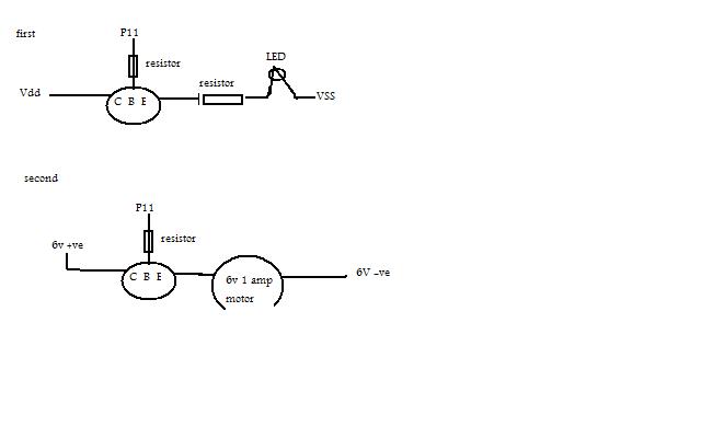
I set up a simple transistor circuit using a BC558B PNP transistor - it seemed to work ok (see example in attached diagram (first)
with the collector conected to vdd, and the emitor to vss with an LED in between. When is pulsed P11 between high and low, good result and the LED flashes on when P11 is low.
now for the problem.
As per the crude diagram (second) I replaced the vdd conection to a 6 volt supply, replaced the LED with a 6V 1a motor, replacing the connection from the emitor to Vss with the negative on the battery - I'd expected this to pulse the motor in the same way as the LED flashed (nb the motor runs fine if connected to the battery directly to +ve and -ve terminals) - the damn thing doesn't even hiccup - what am I doing wrong ??
Should I be using a different spec of transistor or is it more fundamentally stupid of me ?
640 x 400 - 12K
Comments
Look up transistor switch and make sure you have a diode so when the magnetic field collapses you don't blow something up.
http://www.pykett.org.uk/EvolutionTransistorSwitch.gif
You have the PNP transistor connected in reverse for this sort of use (collector to +6V, emitter to load). It's not meant for this although it will work.
I'm assuming that the same essential structure would apply just as well with an NPN transistor, but this will work in reverse ( i.e. will function when High) - I've not been using a common ground, so will explore this circuit further.