Shop OBEX P1 Docs P2 Docs Learn Events
Will this PWM method work? — Parallax Forums

Will this PWM method work?

lardomlardom Posts: 1,659
edited 2010-12-31 19:25 in General Discussion
I found a Phil Pilgrim code snippet I liked because it looks simple and to the point. I want to tweak it for a servo and again for a DC motor. Please tell me if my initial tweak is valid. Phil's original code is in the attachment.
dira[EscPin]~~

 repeat
   waitcnt(cnt += clkfreq / 50)
   outa[EscPin]~~
   waitcnt(cnt + pulse * clkfreq / 1_000_000)
   outa[EscPin]~
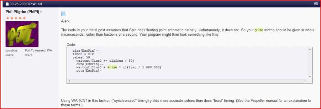
1024 x 348 - 41K

Comments

  • FranklinFranklin Posts: 4,747
    edited 2010-12-30 10:07
    If you have a propeller chip the best way to see if it will work is to load it and try.
  • lardomlardom Posts: 1,659
    edited 2010-12-30 23:29
    My apologies to the forum. My post clearly asks others to do my work for me. It's not what I had in mind when I wrote it but that is what it says. "If you have a propeller chip the best way to see if it will work is to load it and try." I agree, lesson learned, I'll take my lumps.
  • LoopyBytelooseLoopyByteloose Posts: 12,537
    edited 2010-12-31 04:08
    Frankly, I wonder why one should bother with an unhelpful reply. But I have to admit I am more of a hardware freak than a software code reader. It certainly helps to make an effort to understand the code including employing it with hardware before pleas for help.

    Regarding the code and PWM.
    1. It appears to be for R/C servo control and to take one cog. Why so? Waitcnt dominates one cog and the 50Hz base frequency is for R/C control.
    2. It doesn't actually limit the pulse within R/C control ranges of about 1.5ms to 2.5ms, so it may be adapted for longer duty cycles, like 50%
    3. It is a good place to start in principal because it is so simple. Try it with an R/C servo and observe the response or try it with an LED. They explore modifications in rate.
    And 4. There are actually two ways to do PWM [a] the sloppy way and the precise way.

    The sloppy way is to add your pulse time to the overall frequency. The result is that the frequency wanders. Often the code is shorter and just fine for controlling lights.

    The precise way is to have the on pulse and the residual time make the pulse trigger at exactly the same time on each cycle.

    Can you figure out which one the above example is? If so, you are on your way and don't need any help. BTW, I may be wrong about the 50Hz. So you should doublecheck the Waitcnt math before trying this with a servo ;-D
  • lardomlardom Posts: 1,659
    edited 2010-12-31 09:09
    Phil Pilgrim's use of the add assignment operator (+=) should produce a 20ms pulse rate with no drift. The rest of the code controls the pulse width. No fluff. I had to go back and reread page 62 of the "Propeller Education Kit" manual to find out what "+=" did. I don't have a scope to look at it but I believe it will do the job nicely.
    dira[EscPin]~~
    
    dt := clkfreq / 50
    T := cnt
    
    repeat
      T += dt
      outa[EscPin]~~
      waitcnt(cnt + pulse * clkfreq / 1_000_000}
      outa[EscPin}~
    
  • LoopyBytelooseLoopyByteloose Posts: 12,537
    edited 2010-12-31 19:25
    Initally I had a lot of trouble with Spin and the assignment symbols as I never learned Pascal. But as one begins to use it more and more, you begin to see that the clarity of not having the same symbol representing equality and assignment is helpful to seeing what is going on.
Sign In or Register to comment.