

PPM protocol RC tranmitter module control
 bennettdan
Posts: 614
bennettdan
Posts: 614
Hello,
I have been working on a project that uses the plug in TX modules from Futaba RC transmitter radios to send to a Futaba RX receiver. I am going to share what I have so far and hope anyone that has question or suggestions will post them.
I Have used a Basic Stamp 2 to send signals out of the TX and I am now working on the Propeller version.
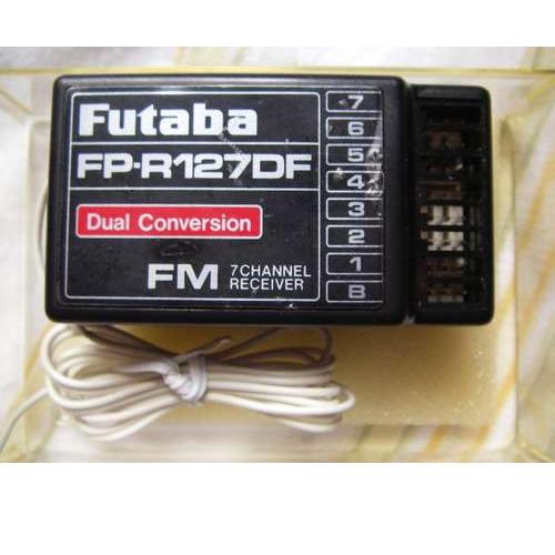
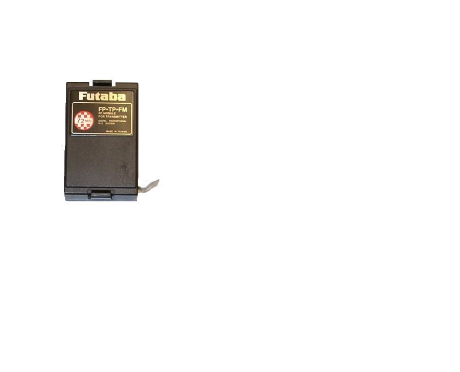
The modules used are the Futaba FP-TP-FM transmitter and the Futaba FP-R127DF 7 Channel receiver.
The Futaba FP-TP-FM module plugs in the back of some of the higher end Futaba radios and allows different frequency and channels to be uses without and entirely new Radio.
The modules can be had in many frequency the 72mHz FM ones like I am using need and antenna but the 2.4gHz modules have the antenna built in but are a little more expensive.
This project allows the long range sending of Servo signals that can be feed directly to a servo or speed controller or read buy and on board Basic Stamp SX or propeller.
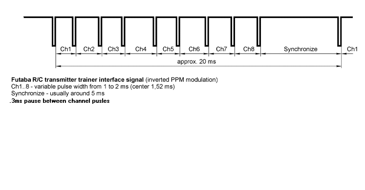
The signals sent are From .7ms to 1.7ms and the a .3ms pause between servo pulses according to the PPM protocol.
I used some code out of the propeller obex called jm_servo8.spin and I have modified it to and renamed it PPM Servo DriverPPM Servo Driver.spin.spin and each line I have modified I add ''Dan to the end of the line.
I was in the middle of testing this out some more when my lovely 3 year old little lady managed to share some of her bring with the propeller and it didn't seem to like it LOL...so I will have to order a new board.
The only thing I don't like about the code is that at the end of sending all the Channel pulses their is a waitcnt that waits for either 10ms 20ms or 50ms preset by the main spin program. What I have plans to do is to add the pulse width of each servo the .3ms pauses then subtract them from the true 22.5ms PPM protocol length that way the pasm loop sends it the signals over and over at the proper 22.5ms rate.
I have included pinout drawings, pictures of the modules and the modified spin program to the post.
Comments and suggestion are welcomed
PPM_protocol.bmp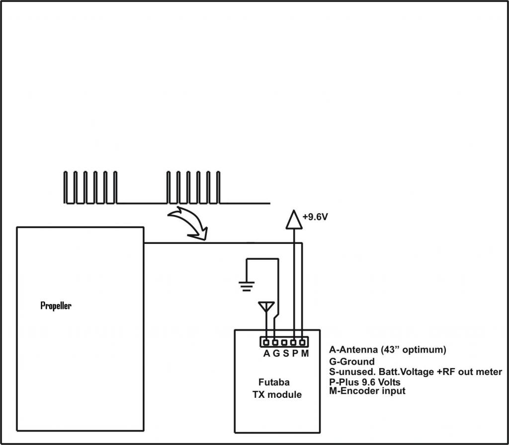


I have been working on a project that uses the plug in TX modules from Futaba RC transmitter radios to send to a Futaba RX receiver. I am going to share what I have so far and hope anyone that has question or suggestions will post them.
I Have used a Basic Stamp 2 to send signals out of the TX and I am now working on the Propeller version.
The modules used are the Futaba FP-TP-FM transmitter and the Futaba FP-R127DF 7 Channel receiver.
The Futaba FP-TP-FM module plugs in the back of some of the higher end Futaba radios and allows different frequency and channels to be uses without and entirely new Radio.
The modules can be had in many frequency the 72mHz FM ones like I am using need and antenna but the 2.4gHz modules have the antenna built in but are a little more expensive.
This project allows the long range sending of Servo signals that can be feed directly to a servo or speed controller or read buy and on board Basic Stamp SX or propeller.
The signals sent are From .7ms to 1.7ms and the a .3ms pause between servo pulses according to the PPM protocol.
I used some code out of the propeller obex called jm_servo8.spin and I have modified it to and renamed it PPM Servo DriverPPM Servo Driver.spin.spin and each line I have modified I add ''Dan to the end of the line.
I was in the middle of testing this out some more when my lovely 3 year old little lady managed to share some of her bring with the propeller and it didn't seem to like it LOL...so I will have to order a new board.
The only thing I don't like about the code is that at the end of sending all the Channel pulses their is a waitcnt that waits for either 10ms 20ms or 50ms preset by the main spin program. What I have plans to do is to add the pulse width of each servo the .3ms pauses then subtract them from the true 22.5ms PPM protocol length that way the pasm loop sends it the signals over and over at the proper 22.5ms rate.
I have included pinout drawings, pictures of the modules and the modified spin program to the post.
Comments and suggestion are welcomed
PPM_protocol.bmp


Comments
Edit: Added a bit of error trapping and a feature that lets one use an array of values to set the servo positions
The code works great I had to adjust the min and max values to .7ms and 1.7ms then it worked without a problem it even is responsive down to 12ms overall frame timing with my Futaba transmitters. This should help people get long range RC control to their projects for a very good price used 72mHz TX/RX modules run around 15 to 30 dollars and a new 2.4gHz can be had for around 50 and up depending on if the unit has sattelite antennas. I am going to post my BS2 code and my Propeller code and also going to link to this Thread in the Projects I have some more testing and I might also work on adding the PCM protocol also. Thanks
Here's snippit that shows that adjustmet:
rdlong  servotix, hub                   ' get channel timing from hub
                        add     hub, #4                         ' point to next channel
                        sub     servotix, pulsetix              ' correct timing for lead/lag pulse
I tested the code with a scope and have verified that the servo position value you send is what you get (edge-to-edge of the lead/lag pulses).
Thanks I didn't fully look at your code before I tested it sorry...it actually worked fine both with .7ms to 1.7ms and 1ms to 2ms and my servos had the same travel but the center was off just a little, but not all servos will have as much travel as mine and I was lucky not to have ran the servo to much to one side.
This is an interesting project. I've often thought it would be great to be able to make a custom controller for my RC airplanes and helicopters.
I haven't looked at your code yet but I'm guessing the PPM protocol is also used in the communication link through a "trainer" cord. A year or two ago, I wanted to control a RC robot with a Wii nunchuck so I simulated the signal put out on the trainer connection. It worked pretty well. I'll compare it with your code so see if they're doing the same thing.
I recently tried a different route at making a custom RC controller. I received a Blade mSR helicopter for Christmas (it's a lot of fun). Even though I have several Spektrum DSM2 transmitters, I opted for the "Ready to Fly" version instead of the "Bind and Fly" version. The RTF version came with a little four channel transmitter. The transmitter had two circuit boards inside. The main board had the joysticks, buttons and switches on it. The second board was about the size of a postage stamp (or exactly the size of a satellite unit of a Spektrum receiver). I found information online about the protocol the main board uses to communicate with the transmitter module. I desoldered the transmitter module from the main board, and relatively soon, I was flying a RC helicopter with a Wii nunchuck. I started with a (easy to fly) Blade mCX I received for Christmas two years ago but now I can also fly the mSR with the nunchuck.
I use the accelerometer to control the throttle and yaw. The pitch and roll are controlled with the joystick. It's pretty fun (and really difficult) to fly a helicopter with one hand.
I have some old Futaba radios. I think I'll try your code out on one to the transmitter modules. It would be great to have more options for making custom controllers.
Duane
I looked at your code because I am also interested in a similar RC transmitter application. I am not very familiar with propeller spin or assy. but I have been looking over manual. I have a few questions if you could be so kind to answer.
1. Am i correct that the assembly code is started in a new cog?? Is that why Org is 0 top of the cog ram? What is the statement < fit 492 > and how is it calculated? do variables used in assembly routines have to be within the assembly code section?
2. how is servotix loaded into the hub ram?? I don't see that as a spin VAR. I guess I am not clear on how to differentiate between hub ram and cog ram.
Thanks to all. Sorry for beginner questions, I am still studying so probably more questions
Yes; Spin and PASM programs run in separate cogs (processors).
FIT ensures that the PASM code will in fact fit into the cog space. 496 (corrected per Cluso's catch of my typo) is the largest possible program -- no need to calculate.
Yes, because they are used in their own processor.
It's not. servotix is a local (to the PASM cog) that is the duration of the current channel. The PASM cog reads this value from the hub array called servo[]. One of the parameters setup in the PASM code is the hub address of that array. These lines read the current from the hub and then point to the next channel (hub is a variable that holds the address of servo[]).
rdlong servotix, hub ' get channel timing from hub add hub, #4 ' point to next channelAs it turns out, my January article in Nuts & Volts discusses this. You can view that article here:
-- http://www.parallax.com/Portals/0/Downloads/docs/cols/nv/prop/col/nvp10.pdf
Hopefully, Dan won't consider this a hijacking of his thread; if he does you should start a new thread on programming versus the workings of this particular object.
The fit 492 (normally 496) is to check the pasm code is within the cog space which is 496 longs as the remaining 16 are resrved for registers such as DIRA, etc. Spin code resides in the hub memory and a pasm interpreter runs in the cog to execute the spin code. The interpreter code is loaded from hub rom automatically. There is a lot more info in the stickies at the top of this forum and at the home page.
bennettdan: This is a very interesting project. I am part way through a Quadcopter design and this could make an interesting way to control the quad. The Wii Classic Controller has two nice joystick pots and this can be interfaced to the prop easily using the I2C protocol. The Wii Nunchuck also is I2C and the accelerometer can be used for control. A few nice combinations here.
Thanks for catching that -- I thought something looked fishy; must have been celebrating the holidays too heartily the day I wrote that program!
I have one of those (with end hacked for connecting to a custom circuit) and am about to start experimenting with it.
JonnyMac I don't mind the high jacks when the info is useful as it usually is coming from you...also you should post the PPM code in the OBEX
Cluso99 this PPM transmitter code is very useful because the transmitters and receivers from the RC world are long range and a good price. I have seen your thread on the Quadcopter and plan to build one soon myself that is why I started with the PPM code. I right now have a FPV (First Person Video) helicopter I plan to control with a custom chair simular to this one.
http://www.heli-chair.com/
Dan
I have just begun but I want to build a custom control panel arranged with high quality switches/joysticks/pots in my own design read those with the propellor then use a cog to feed the ppm signal into a rc transmitter module like corona or futaba. I have written a little code but mostly chips like the 8051 back in the day. I am mostly comfortable with hardware. The propeller is a really neat part, I look forward to getting my demo board and playing with it.
Thanks for the nice welcome, hopefully someday i will be able to contribute as well.
Check out the Heli chair link in my previous post I like his chair setup but I didn't want to use the buddy box I plan to use a corona 2.4ghz transmitter module myself but make sure its for a PPM Futaba or JR transmitter because PCM is a different protocol that is not quite as robust as the PPM.
Dan
Did you ever try the trainer port Duane?
Can this be modified for 16 channels? Only 6 are needed but I think the trainer port is looking for 16.
EDIT: I can configure the Taranis to "listen" for a set amount of channels so 8 channels is more than enough.
Time to hack some controllers!