

Help Figure out how this LW61076 RF 120v relay manages channel
 Brann Fenix
Posts: 57
Brann Fenix
Posts: 57
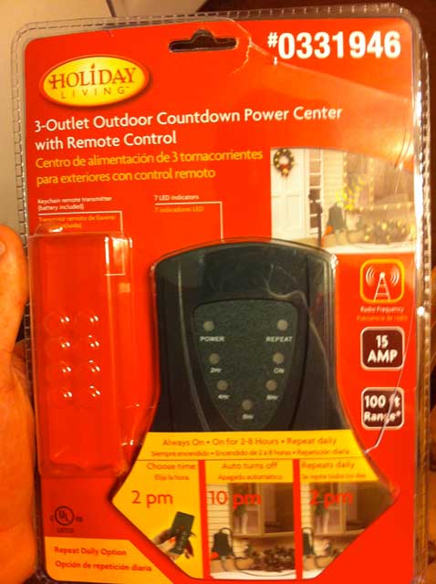
I saw these on 60% clearance at Lowes and instantly thought of some great ways to use them with my current propeller project. These relays are rated for 120v@15Amps with an RF remote that has pretty good range in my quick tests as well as being weather resistant and UL listed. In the past I have rigged up some outlets with solid state relays to switch household items on/off with success. While that has worked fine these are certified and safety approved in one neat 3 outlet package and can be triggered wirelessly.
The issues:
They appear to be made in at least 3 RF channels as noted by a sticker on the unit and remote. My store seemed to have a glut of channel 0 units and one single channel 2 unit. I bought up all I could get my hands on at the $7.19 price tag figuring it could be a good project. At best I would like to be able to figure out how to change channels and integrate some form of single multi-channel remote unit into my project to have the propeller control the various channels of units scattered throughout the area. At worse I would just like to be able to turn a channel 0 unit into a channel 1 or 2 unit and trigger the different remotes with my prop using more pins than I had hoped.
What I know so far:
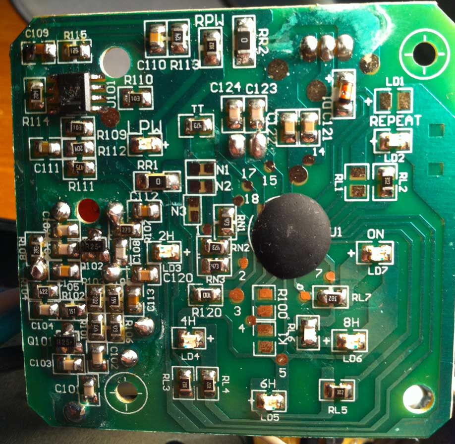
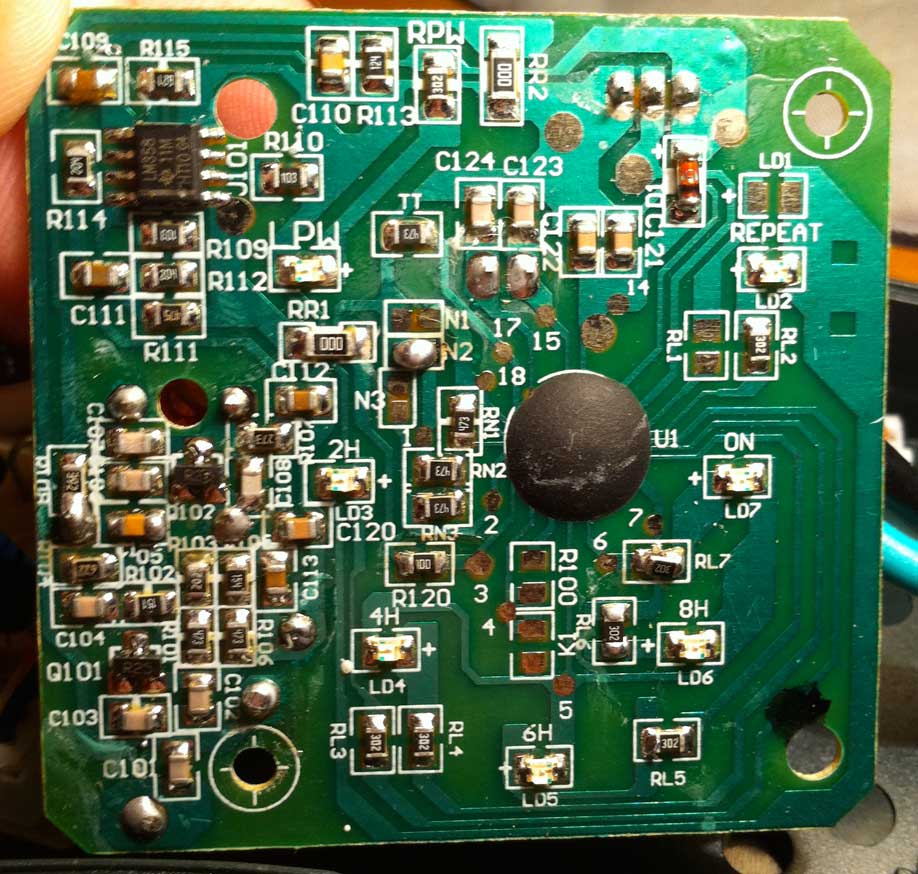
The RF receiver/relay half of the device was very easy to open via 5 screws and a tiny bit of silicone. It is split into two boards with one having all the RF parts and the channel number stamped onto it. The 2nd board is the magnetic relay along with the120v outlets.
I have included some pretty clean high res pictures of the RF boards from the channel 0 and 2 units. Of course the RF controller is covered in black epoxy... but where would the fun be if we could just pull a datasheet? :P
After looking at the boards the only difference I could see was RR1 and RR2 on channel 0 having a marking of 0 and channel 2 having the 000 marking. I am no wiz with RF by any means and sadly do not own most reverse engineering gear like a scope or logic analyzer, but could it be that simple? Maybe I am just fooling myself here, but if all that selects the channel is a different sized resister at RR1/RR2 that would be pretty sweet.
Input?

The issues:
They appear to be made in at least 3 RF channels as noted by a sticker on the unit and remote. My store seemed to have a glut of channel 0 units and one single channel 2 unit. I bought up all I could get my hands on at the $7.19 price tag figuring it could be a good project. At best I would like to be able to figure out how to change channels and integrate some form of single multi-channel remote unit into my project to have the propeller control the various channels of units scattered throughout the area. At worse I would just like to be able to turn a channel 0 unit into a channel 1 or 2 unit and trigger the different remotes with my prop using more pins than I had hoped.
What I know so far:
The RF receiver/relay half of the device was very easy to open via 5 screws and a tiny bit of silicone. It is split into two boards with one having all the RF parts and the channel number stamped onto it. The 2nd board is the magnetic relay along with the120v outlets.
I have included some pretty clean high res pictures of the RF boards from the channel 0 and 2 units. Of course the RF controller is covered in black epoxy... but where would the fun be if we could just pull a datasheet? :P
After looking at the boards the only difference I could see was RR1 and RR2 on channel 0 having a marking of 0 and channel 2 having the 000 marking. I am no wiz with RF by any means and sadly do not own most reverse engineering gear like a scope or logic analyzer, but could it be that simple? Maybe I am just fooling myself here, but if all that selects the channel is a different sized resister at RR1/RR2 that would be pretty sweet.
Input?
478 x 640 - 39K

918 x 896 - 124K

918 x 874 - 134K
Comments
Isn't this one of those 433MHz remote switches? If so, you can easily control them via the Propeller and the Parallax 433MHz transceiver: http://www.parallax.com/tabid/768/ProductID/582/Default.aspx
In this case, all units are using one and the same RF channel (433.92MHz), and N1-N3 is the unit encoding number, i.e. a digitally transmitted identity.
You nailed it with the N1-N3 jumpers. Once I look at them again and noticed the jumpers I wanted to slap myself. Seems I was a little too focused on component differences to not notice something that simple. I was able to change this pile of channel 0 units into 0-3 units with ease. I will need to look into getting them working with the Parallax transceiver a little bit down the road because that would greatly reduce the size of my project. Thank you again for the quick reply that was right on the money.