

pH Sensor Interface
 atrobins
Posts: 4
atrobins
Posts: 4
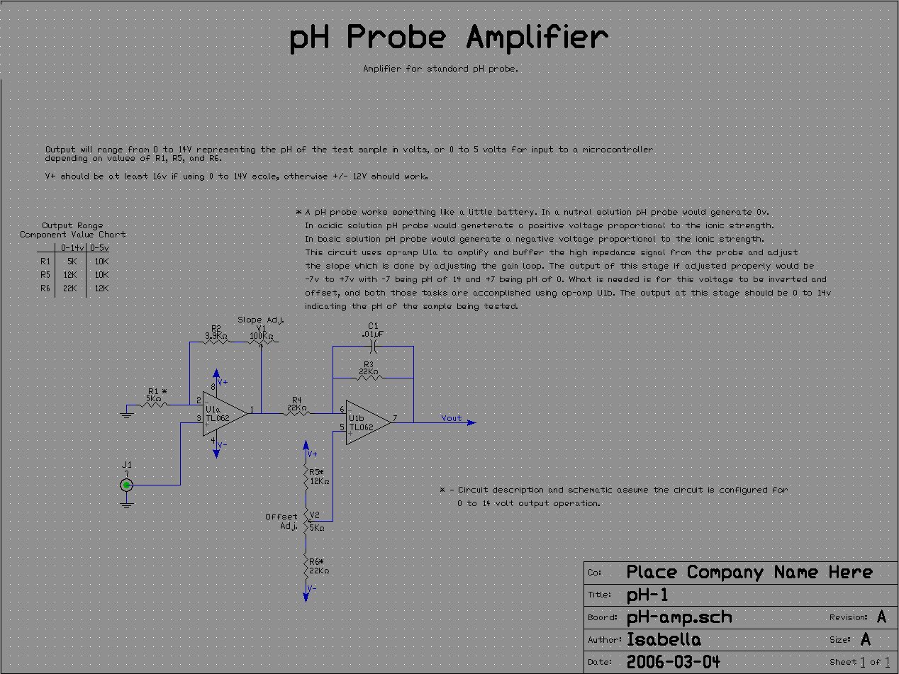
I have been working on a Saltwater Fish Tank controller for several months now. My latest addition to the project is a pH Sensor. I have built the pH circuit below.
http://blea.ch/wiki/images/2/24/PH-sch.jpg
Everything seems to work properly with the circuit as when i check the output with a volt meter I get the proper voltage between 0 and 5 volts for the pH of the tested solution. My plan was to use a PCF8591 A/D Converter to convert and send this signal to a BS2p using I2C communication as this seems to be a well documented chip and sample code was available. This is where my problem comes in. I am using the sample code avalable in the BS2p Plus Pack Kit.
www.parallax.com/dl/docs/cols/nv/vol3/col/nv79.pdf
The results I am getting are very unstable. For example with the voltmeter I read a constant 2.88V. The debug screen from the sample code produces a voltage ranging from 2.5V to 3.1V that changes every time the code reads from the A/D Converter. I am stuck! I have tried everything I can think of from loose connections to common grounds to tinkering with the code. When I bought the PCF8591 Chip I got two. I have tryed both with the same results. Does anyone have any sugestions as to where I may be missing something. Thanks in advance for any help.
Comments
Rick
Or, as Will Smith might say in Bad Boys 3, "POP A CAP IN ITS RAGGEDY Smile!"
Sorry, I couldn't resist.
The filter cap erco recomended may be an option but I'm not sure what size and where to add it on the circuit.
Thanks agan and let me know what you think.
Look at these links to see what others have done. One of them is a single supply version.
http://www.66pacific.com/ph/phschematic.htm
http://www.electro-tech-online.com/attachments/electronic-projects/21692d1218729019-ph-amplifier-micro-ph_amplifier.pdf
Notice the bypass caps at the opamp power supply pins, the filtering at probe input, and the much larger cap in the feedback path of the second opamp. The ph probe output impedance and the opamp input impedance are very high and very susceptible to noise pickup. Don't do this on a breadboard and expect it to work well. What form is this circuit in?
For now, stay with the batteries until other problems are eliminated.
Rick