

How to hack servos...
 Ravenkallen
Posts: 1,057
Ravenkallen
Posts: 1,057
I don't know about the other forum members, but i tend to hack my servos for continuous rotation in a different way then most...
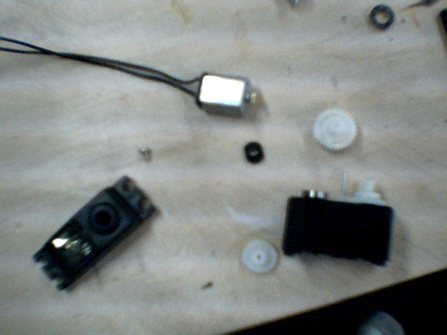
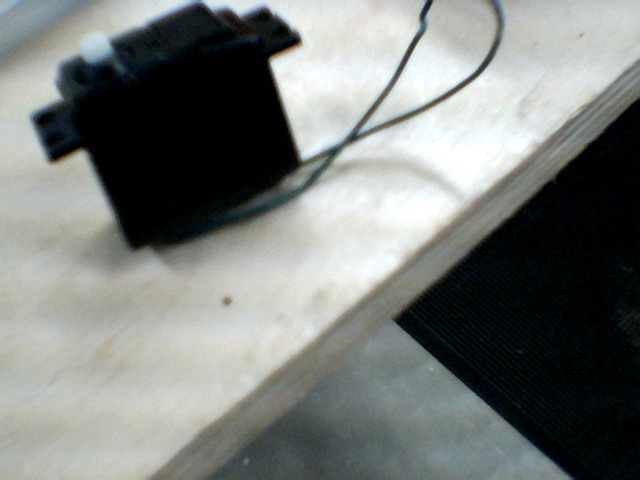
1: First unscrew the servos completely and put the screws aside...
2: Carefully remove the housing from the top and bottom(Try not to loose the gears)
3: Pull out the drive electronics/ motor carefully and put aside
4: On the main gear(located on the feedback shaft) you should see the protruding "tooth" that gets in the way of the other gears(this keeps the servo from moving to far in any direction). You must carefully remove this tooth in a way that it doesn't affect the rest of the gear. I used a power drill to drill a hole through it and then bent the rest off with pliers.
5: Down in the feedback mechanism, there will be another tooth to remove. I remove it by taking the whole thing out and using pliers(and brute force) to literally bend the tooth or break off the whole feedback doohickey. That should leave you with the feedback shaft that is able to rotate 360 degrees
6: Take the drive electronics and unsolder the motor from the board. Solder your own wires to the motor
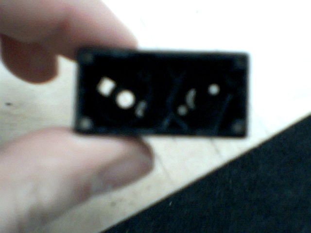
7: Put everything back together the way you found it(put the motor back in, the gears back in place, etc..) you may have to drill a bigger hole in the bottom to fit wires
8: Cool, now you have a motor with gears")
What you have now is a nice little DC gearbox that doesn't need sophisticated electronics to drive it. They are great for(slow) robots and any application that needs high torque.. Did i mention it is also cheap.. Sorry about the bad quality pics. I am using a dorky key chain camera
1: First unscrew the servos completely and put the screws aside...
2: Carefully remove the housing from the top and bottom(Try not to loose the gears)
3: Pull out the drive electronics/ motor carefully and put aside
4: On the main gear(located on the feedback shaft) you should see the protruding "tooth" that gets in the way of the other gears(this keeps the servo from moving to far in any direction). You must carefully remove this tooth in a way that it doesn't affect the rest of the gear. I used a power drill to drill a hole through it and then bent the rest off with pliers.
5: Down in the feedback mechanism, there will be another tooth to remove. I remove it by taking the whole thing out and using pliers(and brute force) to literally bend the tooth or break off the whole feedback doohickey. That should leave you with the feedback shaft that is able to rotate 360 degrees
6: Take the drive electronics and unsolder the motor from the board. Solder your own wires to the motor
7: Put everything back together the way you found it(put the motor back in, the gears back in place, etc..) you may have to drill a bigger hole in the bottom to fit wires
8: Cool, now you have a motor with gears
What you have now is a nice little DC gearbox that doesn't need sophisticated electronics to drive it. They are great for(slow) robots and any application that needs high torque.. Did i mention it is also cheap.. Sorry about the bad quality pics. I am using a dorky key chain camera
Comments
Hacks are quite fun and empowering. I've got my eye on a Wall-E bot at the Disney site for a hackable package as it is only $49 USD when other robot platforms are so much more.
But, be advised - NOT all servos are hackable. Some don't have complete circular gears for full rotation and others may be constructed in ways that make a changeover quite difficult.
Hacking is fun and certainly has its place in learning and creativity, but at times one can hit a brick wall. Parallax sells specially made Futaba servos with an adjustment screw to set zero rotation. Having done the hack, I find these are as good or better. And of course, once you hack the servo - it is no longer of any use for its original task. I have an R/C airplane that needs traditional servos.
The servo is just a handy package for a motor in such a hack. Some people provide just two wires out of the motor and have the H-bridge outboard. Others prefer to have an 'inboard H-bridge' and several more control wires going in and out.
I'd like to see what you come up with for an H-Bridge controller. Just for a design comparison with what I have come up with.
http://static.electro-tech-online.com/imgcache/572-hbridge.gif
http://www.beamitaly.solarbotics.net/library/circuits/driver_hbridge.html Go here.
One very often overlooked point about adapting servos to use with an H-bridge is that they then can employ PID control. I've never seen anyone bother to attempt PID control with PWM.
Low power H-Bridges are very forgiving and can be build in a variety of ways. BEAM websites had years and years of discussion and development of nuance for extreme low power H-bridges. And of course, it is extremely easy to impliment a relay H-Bridge is timing isn't critical.
BTW, I have several pairs of good DC motors for robotic that sit around ignored - just because they are harder to mount to a chassis than an R/C servo or they don't have the right gear ratios or they don't have an easy way to attach wheels or a level arm.
Soo... hacking the servo can make one move ahead quite easily.
But from my many posts on the subject, no one except me cares about my beloved dynamic braking, so I'll take my low-power, polarized coil, high-efficiency relays and go home...
@Erco... i am not ignoring you, i just don't have any relays in my lab. I have been meaning to buy a couple, but i have never got the chance. Any recommendations for a general purpose relay? The voltage drop is annoying, but i like transistors
Ravenkallen:...Thanks for sharing your H-B circuit. I came up with an almost identical circuit.I just added some EMF diodes.I even choose the TIP120's. I was just wondering if we all were on the same page with H-B controllers. I didn't want to fall behind. Thanks again.
'
I'm looking forward to see what loopy... has to say about the need for different transistors?
It's on sale right now for $39!
Cheapest & quickest option is to dig your discarded servo control electronics out of the trash can. It's hard to second-guess the manufacturer!
Generally servo motors don't do well with voltages much higher than 7 volts, but that limitation may be because of the internal control boards failing. The motor itself and in stand alone use might handle 9-12volts. Much depends on the quality of the brushes. Of course, it is also possible to melt the copper wire windings if you put enough power through the motor as well.
http://www.solarbotics.com/motors_accessories/gear_motors/
The control inputs are amplified to increase power. I've doubts that 12volts will seriously wear out the motors with the internal electronics removed.
Regarding boosting voltages, Pololu seems to be filling that niche in the market place with a wide range of tiny regulator boards that fit a range of needs.