

Boost converter
 Zap-o
Posts: 452
Zap-o
Posts: 452
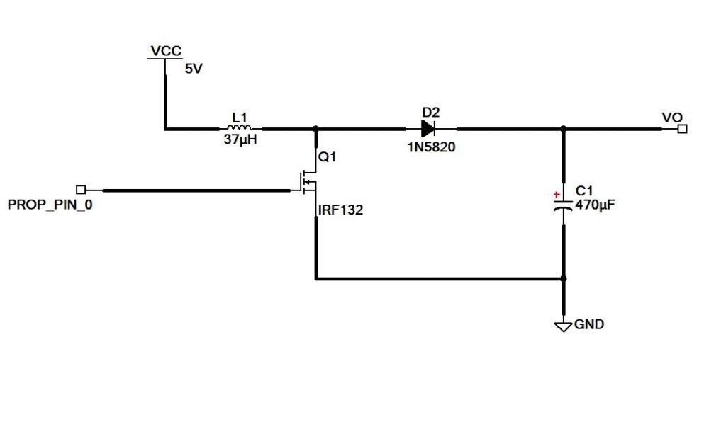
I am trying to make a boost converter using an input power supply of +5 Volts 20 amps. My goal is to convert that close to 15 Volts, 1.5 amps. The problem I am having is that when I apply a load (Vo) the voltage drops under 15 Volts. Is there anything you see that I am missing? I think that the voltage is suppose to drop as current increases, Ohms law, but how does a switching supply keep the voltage the same? Am I even close? I have tried placing a zener diode on (Vo) and that did not help.
Take a look at my schematic.
Take a look at my schematic.
1024 x 630 - 24K
Comments
Look at the documentation for sigma-delta ADC in the Application Note on the cog counters (AN001).
I just had a look at the datasheet for the IRF132, OMG! this is a an old beast in a TO3! I doubt it will be up to the task and many newer MOSFETs in much smaller packages are at least 10 times better. The IRF132 Vgs is quoted at 2 to 4V but this just means it starts to turn whereas you need it to turn on as hard as it can (and it's not so good at this either) so you really need 7V or more and a driver to supply the peak currents for the gate capacitance etc etc. Now you see it's starting to get complicated.
Take my advice and if all you want is to have it work then just use an OTS switching chip that will do the job along with the recommended components using the CAD tools the manufacturer supplies (LTspice, Webbench etc). By all means though keep playing with circuits even just for the educational value.
a 15kHz signal at about 75% duty cycle will get you in the right ball-park. ... 15.72V @ 1.6 Amps
The problem is, that the inductor will need to handle at least 10Amps (20 to be safe) and dissipate nearly 27 Watts of heat.
The IRF132 is happy at just 203mW assuming that the Rds ON is close to .25 Ohms.
I thought that since the inductor is being modulated (from the mosfet) that the DC power loss is minimal.
Also is-int current the same in a series circuit? The inductor and the diode are in fact in series with the supply and the output. So I am confused on the 10+ Amp value you fellas are throwing at me
Please shed some light my way
I just put the schematic that you provided in a simulator.
Looking at the datasheet for the MOSFET and DIODE, I plugged in the values.
Most of the current through the inductor comes from the amount of time the inductor needs to be energized (75%)... this was 8.something Amps on the simulator.
On the output I placed a 10 Ohm resistor for a 1.5 Amp load at 15V
Starting with a 50/50 duty cycle, I adjusted the frequency until I reached a peak value.
Then adjusted the Duty Cycle.... 75%/25%
Playing around with these circuits, I have never got anything to work over 1 amp. I have great admiration for the engineers who design switch mode supplies. With a CRO it is possible to see that square waves are not really square waves. Things like the input capacitance on the mosfet become significant as you want to move that up and down very quickly. There are gate driver chips that do this for you.
You can drop the frequency but then the inductor becomes bigger. And as mentioned before, you need thick wires on that inductor. How big is your inductor, and what is the rating in Amps?
Yes, this is a conservation of energy problem. Energy is converted from volts to magnetism in the coil, then back to volts. I can write some more about this if you want to understand the theory better. But energy can be lost too, eg through resistance in the winding of the inductor. So a tiny 37uH inductor with a 100 ohm resistance will lose more energy to heat than a 37uH inductor with a 0.1ohm resistance. You can work out how much with V=IR where I=5A. In fact, with 100 ohm inductor, the volts =5*100=500, which is so much more than your 20V that you get nothing out. However, the same circuit might be able to produce 10mA with no problems.
Also - once you have worked out the optimum mark/space ratio, you can run the circuit for a while, then turn it off for a while once the capacitor is charged. So run it till the cap gets to 20V, then turn it off till the cap falls to 19V. This means there is another part to the circuit you need to build - some way of measuring the output volts. With no load on your circuit and no feedback, the output could very quicly go to 50V or more, and then the capacitor will fail. For any circuit you build, you can put a test load on the output and then you will find there is an optimum efficiency for a certain frequency and a certain mark space ratio. One you have found that peak, it is better to always run the ciruit at that frequency and mark space ratio, and turn it on an off as required. I hope that makes sense!
My next question is, how do I calculate the current required to charge the gate of the mosfet. Say a P-chan to an N-chan. Is there a formula or general rule?