

Op amp/Regulator math
 Erik Friesen
Posts: 1,071
Erik Friesen
Posts: 1,071

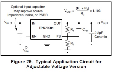
I need a dual voltage regulator. What I want to do is set R1 & R2 so I get an output of 4.5V, lets say, then add another resistor to FB, which I can drive using an output from my micro, to give me an output of either 4 or 5 volts. I could do the math easier if I just let the pulled the pin low, or let it float, but I want to drive the pin high and low. This is regular op amp math, I know, but I have a tough time getting the three ways in my head.
374 x 238 - 32K
Comments
Problem is a single resistor value will not allow you to go from 4.5V with the pin in hiZ state to 5V when it is high and 4.0V when low.
I hope this isn't the voltage regulator that supplies the micro. If it is, the level of the high output will change, and you will get oscillation. If that's the case, use the output pin to drive a MOSFET to pull the bias resistor low or to let it float.
-Phil
-Phil
This may be what you are after. You are right, this is op-amp-type DC feedback math.
This is from basic principles. The current i3 is the sum of currents i1 and i2. (Kirchoff's current law) Note that the currents have associated reference directions, and a current is positive if it flows in the direction of the arrow and negative if it flows against the arrow. (Pleeeeease, no one break in to argue about which way the electrons are hustling along!) Each branch obeys Ohm's law, that is, the current through the resistor is I=V/R, and the equations show that the V's are differences. V2 is the input from the Prop (it is a Prop, right?) at either 3.3 or 0 volts. Plugging the branch equations into the node equation gives the 5th equation in the picture.
Now turn that into two equations by plugging in the desired voltages: 1) Vo=5V when V2=0V, and 2) Vo=4V when V2=3.3V. The reference for the regulator is always V1=1.193V, and feedback will act to make that true. Now you have two equations in three unknowns, R1, R2 and R3, but as is always the case, you can find two resistor ratios, and the absolute values are open to selection based on other criteria such as current drain or secondary effects. When I solve it, I get
R3 = 3.3 * R1 and R2 = 0.346 * R1
(the details and veracity check are left to the reader :cool:!
Its not a prop. I feel a little guilty about using parallax forums. These forums have a level of patience, and knowledge that does not exists on others, therefore I like using it.
@Phil. You can read the app notes I am using here - http://www.alphasense.com/pdf/NDIR/AAN_202-03.pdf
I considered pwm, but my gut says this is a cleaner method. Why set it up to use pwm when I only need the full 5v 2min a day? It has to do with keeping a halogen lamp from plating out. ref http://www.alphasense.com/pdf/NDIR/AAN_205-02.pdf
IMO. There is never a reason to feel guilty about using this forum to discuss fundamental notions in electronics. As you phrased it, it is regular op-amp math.
I agree with your solution, given that your control voltage is 5V instead of 3.3V:
Vo = 5V or 4V, V1 = 1.193 and V2 = 0V or 5V.
R3 = 5 * R1 and R2 = 0.334 * R1, so,
R1 = 100k, R2 = 499k, R3 = 33.2k using standard 1% values.
The two defining equations solved for those ratios are:
(5 - 1.193)/R1 + (5 - 1.193)/R2 = 1.193/R3 for 5V output
(4 - 1.193)/R1 + (0.0 - 1.193)/R2 = 1.193/R3 for 4V output
Note that with resistor values that high, the bias current of the regulator feedback pin may have to thrown into the equations for best accuracy. I see that the bias current of the TPS79901 is bounded by +/- 0.5 µA, so the error due to the bias current will be about +/- 0.05 V at the output (100kΩ * 0.5E-6µA).
Reasons to use PWM:
1. It uses fewer parts: just a MOSFET, assuming your micro can produce the requisite PWM waveform.
2. It uses less power: no (Vi - Vo)*I losses from the regulator.
3. You can soft-start the filament, thus prolonging the life of the lamp.
-Phil
I still like the challenge of getting this stuff figured out, whether or not pwm.
Another approach to the voltage control would be a digital pot controlled by the µC.