

Proto Board Power
 Humanoido
Posts: 5,770
Humanoido
Posts: 5,770
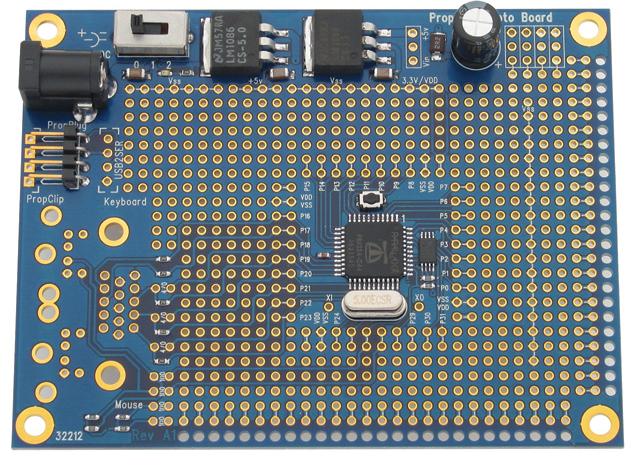
The goal is to power the Parallax Proto Board with slightly less power by NOT including the 5-volt and 3.3-volt regulators. An external power supply with 3.3 volts would be used. The question is, where to feed in the 3.3 volts without it feeding back into the on-board regulators? Where to connect 3.3 volts and ground on the board?
Comments
This is one of the easiest things to do, as far as electronics.
I'll give you a hint, find the 3.3v regulator output. (the leg that outputs 3.3v)
Heres another hint, look up the part number for the 3.3v regulator and find the datasheet for the regulator.
Then use your soldering gun to lift the 3.3v leg up off the pcb. The spot that the leg you just lifted, on the pcb is where you will bring 3.3v in externally.
Gnd can be connected to any gnd location on the pcb.
If your worried about frying things, just use cheap fuses rated at 200ma or so, when you feed 3.3v into each pcb.
I did a quick look at the layout and saw that the only thing 5v is used for are the vga/mouse/keyboard connectors.
So unless I missed something you should be ok just lifting the 3.3v regulator output leg, and then supplying 3.3v into that same pad, under the 3.3 output's leg. If you lift the leg of the 3.3v regulator output more than once, or lift it too far, it will break off. Although its not easy to replace regulators, they are really really cheap.
Now that changes things. Someone who knows linear regulators better should chime in here. I would just try it with a few boards, leaving the 3.3v regulators in place, now that I have a prop scope, I would look at the input of the 3.3v regulator to see if its doing anything. I would also look at the 5v regulator and see if its doing anything.
Because of its price, no one has any excuse anymore to not know what sharks are in the quantum foam. Electron potential tools like the prop scope should be in your suitcase.
Bill
But, back voltage/current through a voltage regulator is generally a failure mode - plain and simple. The documentation indicates this when it discusses the installation of bypass diodes to prevent backwards current from destroying the regulator with larger capacitors on the output than on the input.
Also, that servo motor capacitor needs to stay out of the configuration as it is huge! It can offer up a hefty back current on its own.
And Chuckz has an idea - I just don't know what it is.
I'd just remove the output pin AND use the line of 3.3v and GND holes near the top edge to provide a new source of 3.3 volt power. It would have been much easier to do modifications if Parallax had the 5 volt regulator independent of the 3.3 volt regulator. Maybe one day they will do like the Hydra. And maybe even improve on it by allowing one to eliminate the +5 Volt regulator and/or the +3.3 Volt regulator when one wants to explore alternative low power solutions.
I'm wondering whether an amplifier circuit could step down or step up the voltage instead of using a regulator.
On second thought, it looks quite feasable to snip the legs off the regulator with a side cutters. (this would save some leakage current) In this case just snip the legs off and run your 3.3volt supply to VDD.
Lawson
While ALL my reading of PDFs somewhat indicates this is NOT a good idea, there is one example of success that keeps coming to mind.
The Parallax Basic Stamp has a 5 volt regulator with a pin that is frequently exploited for either +5 volts out or to bypass the on board regulator. This would seem to indicate that if one DOES NOT substantially exceed the regulator's output voltage and one DOES NOT short the input side of the regulator, insertion of good regulated voltage from another source may do absolutely no harm. Of course, this may be true of only some regulators, so some destructive testing with the Prop boards might be required.
Are you willing to run a test for the sake of everyone?
So I am now advocating that one doesn't really have to do anything.
CumQuaT's solution is another good alternative that needs to be tested - a bypass diode on each of the regulators may offer adequate safety. The board's chain of voltage regulators retains its functionality while being enhanced.
@Chuckz
You can use op amps to regulate voltage, but in this context they are hardly a useful suggestion. Historically, the 741 was originally used for voltage regulation before everyone started making voltage regulators in their own package. You can Google for images of voltage regulation and find many examples of these 'old time' circuits.
Does anyone care? If not I'll just wait until I really need to know.
Last night I reconfigured things to go back to using the 7.5V external power supply to make sure the 5V regulator still worked, and the board had no problem running. But later today I will verify that the 5V regulator is still producing 5V (and not some other voltage) with a DVM.
I also know that The Gadget Gangster Propeller Platform battery board connect the 4 cells (either 6V or 4.8V) directly to the 5V line on the Propeller Platform board (the 5V regulator output), and I haven't heard of any problems there either.
So I have had modest success on the Demo board -- YMMV.
I've powered a propeller board by connecting four NiMH cells (with a voltage range from 4.8 to 5.2 volts) directly to the 5 volt pin of the 5 volt regulator output with no bad effects at all.
Before I did that, I did my best to research its possible effects. I looked at the regulator data sheet,but it said nothing about how the circuitry would take to receiving external voltage and current at the output pin. I asked here, and on other forums, but nobody had a definitive answer of whether that was an ok practice. So I tried it, and had no problems.
On another project unrelated to the propeller, I discovered that the 5 volt regulators I was using do not draw current to pull an externally applied voltage down to 5 volts, reinforcing that this may not be a problem. And so far, it has not been.
Has anyone experienced failures from doing this?
There is no definitive answer from any documentation. But we have reports on no apparent damage to the 5V regulator from being ignored. So I strongly suspect there won't be any ill effects if a good regulated 3.3 volts is applied directly to the Propeller chip.
The risk of damage seems to be a myth. But, bear in mind that not all regulators are the same internally. I am still wondering if the regulator on the board consumes any power at all, or is entirely blocked by its own internal circuitry.
Can you provide a PDF that states explicityl what you assert?
The BEST solution is to install a protective reverse voltage by-pass diode between the Vin and Vout pins on both the 5 volt and 3.3 volt regulators (easily done by soldering on top of the existing tabs). Nothing is lost in terms of function and you now have complete protection from a short circuited Vin while providing power downstream from the Vout pin.
That it! That is ALL of it. Read the PDF for the LM1086s and you will see that this makes sense. Also look at the detailed schematic for the internal parts. And ponder the simplified schematic they additionally provide.
I looked at all the datasheets for the linear regulators for some of the available boards:
Demo Board: LM2937IMP-5.0 and LM2937IMP-3.3
Proto Board: LM1086-5.0 and LM1086-3.3
GG Propeller Platform: LM1085V50 and LM1086V33
GG Propeller Platform USB: LM29150DT50R and LM29150DT33R
From the reading I have done, for these regulators there are two possible ways to damage the regulator by supplying voltage to the output pin:
- Reverse Bias damage to the pass transistor. This happens when the voltage on the input pin is lower than the voltage on the output pin. This reverse-biases the pass transistor, and can damage it. This can happen when the voltage on the input drops faster than the voltage on the output pin (perhaps due to large capacitors on the output pin). Worst case is a grounded input pin, and voltage on the output pin. The recommended protection is to add a reversed diode from the output to the input pin, so that in the reverse-bias condition, the diode shunts the current around the regulator.
- Damage to the voltage regulation feedback circuit
I found a few other data sheets that talked about "reversed-lead insertion protection", which I assume means reversing the input and output leads in a circuit. These regulators have protection for this condition, which was described as protecting the regulator against this "temporary" condition. This would be equivalent to supplying the output pin with voltage, and providing a current path (load) from the input pin to ground.For all the regulators listed above, I found no warnings in the data sheet about applying a voltage to the output pin with no voltage applied to the input; however, the reverse-bias condition can arise if the input pin is grounded.
I believe, based on what I have read so far, and on the one experiment I have done, that it is "safe" to apply the voltage to the output pin as long as the input pin is floating. But I am prepared to be corrected by someone who has more information and knowledge than I have.
Disclaimer: I am a Software Engineer, not a hardware engineer, so the amount of detailed circuit knowledge I have is limited. I am sure there may be regulators that will be damaged if voltage is applied to the output pin with the input pin unconnected, but I have seen no language to that effect in any of the datasheets for these regulators, nor in any other similar regulator datasheets. I would be happy to learn in what situations, and for what kinds of regulators this would be damaging to the regulator.
The sense I get from having read lots and lots of voltage regulator PDFs is that the writers have never been asked this specific application question. So it becomes a matter of trials and observations by us, the user community.
And, since the BasicStamp and several of its clones have been offering a regulator by-pass pin for many years without identifying it as a failure issue - it seems that it just isn't a problem.
In my own case, I damage a lot by rough handling during experimentation. So I will solder the two diodes on that I mentioned above. There is no reason for me not to as they just enhance the ruggedness of the board AND I am not going to try to resell the board as pristine.
Here are some test conclusions about modifying the Parallax Propeller Proto Board for less current draw. The unmodified board draws 10ma. This includes the powering up of two voltage regulators and one power LED. The modified board draws 4ma. It disables the the power circuit from the 3.3-volt regulator back to the barrel jack power input. The reference is one active cog with a 5MHz crystal. The modification saves 6mA for each board. For 100 boards, unmodified use 1 amp. Modified use 400 milliamps. The savings is .6 amp. The test does not separate out the LED from the regulators as the majority of the current is likely across the LED. This was not a necessary part of the test because a power indicator light would not be used. For 20 modified boards, the power draw is 80mA total. Unmodified is 200mA. Proto Board current draw is critical for battery operated robots and devices.
Humanoido Quote: It's more easy than that. Just lift up the middle leg of the LM1086CS-3.3 which is pin number 2 as Vout. No need to solder on anything. There's no short circuit possible because the 3.3-volt circuit is now isolated. Plus, the leg can push back down for re-soldering in the future to return the Propeller Proto Board to its original pristine condition. (It won't break off) To see how this works, take a look at the schematic under Regulators.
When I done this is because
Basic Stamp
LCD / LED lighted display
or Card Reader and the like because of amp draw