

Astrophotograpy Time/Temp/Humidy Data Logger: Will you check my diagram,, please?
 Bill Chennault
Posts: 1,198
Bill Chennault
Posts: 1,198
All--
To support my astrophotography addiction, I need something that will record the time, temperature and humidity while I am capturing photons. Although I think you can buy something like this, what fun would that be?
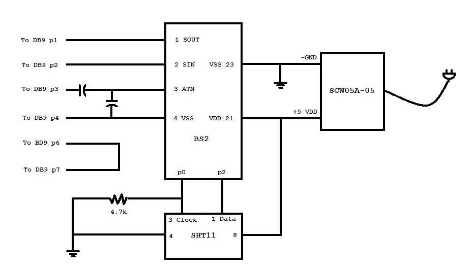
I came up with a BS2 based, Sensirion SHT11 driven design. Of course, it is very simple or I couldn't do it. The time is supplied by my laptop as it looks at the BS2 serial port (via USB). I record date, time, temperature, and humidity each minute with VB6 code. The BS2 code was adapted from the Parallax SHT11 advanced demo program.
Power will be supplied by wall transformer output (9vdc-12vdc???) into an SCW05-05 DC-DC converter via a 2mm barrel connector. (I stuck the PCB on my mill and created slots out of holes for the barrel connector.) I plan to put it into some kind of enclosure with a hole for the Sensirion to mount flush with the surface.
I have thoroughly tested it on a BOE. Now I would like to move it to a RS PCB. I would appreciate your comments regarding what I've done wrong in my diagram.
Thanks!
--Bill
To support my astrophotography addiction, I need something that will record the time, temperature and humidity while I am capturing photons. Although I think you can buy something like this, what fun would that be?
I came up with a BS2 based, Sensirion SHT11 driven design. Of course, it is very simple or I couldn't do it. The time is supplied by my laptop as it looks at the BS2 serial port (via USB). I record date, time, temperature, and humidity each minute with VB6 code. The BS2 code was adapted from the Parallax SHT11 advanced demo program.
Power will be supplied by wall transformer output (9vdc-12vdc???) into an SCW05-05 DC-DC converter via a 2mm barrel connector. (I stuck the PCB on my mill and created slots out of holes for the barrel connector.) I plan to put it into some kind of enclosure with a hole for the Sensirion to mount flush with the surface.
I have thoroughly tested it on a BOE. Now I would like to move it to a RS PCB. I would appreciate your comments regarding what I've done wrong in my diagram.
Thanks!
--Bill
930 x 530 - 28K
Comments
Does that mean I should tie p0 and p2 to ground via a 4.7k (?) resistor? If so, should I tie all I/O pins to ground even if they are unused?
I have (rather crudely) modified the drawing in red according to what I think you wrote. Did I do it correctly? (Attached.)
My setup consists of an AT8IN telescope on an Atlas EQ-G mount. I use a Nikon D700 at prime focus. Guiding is performed with the Orion ST80 and StarShoot Autoguider. Images are captured using ImagesPlus Camera Control running on an old Dell 530 (531?) under XP. I process images with ImagesPlus Processing and Nikon NX2.
The problem I am trying to solve concerns matching dark frame temperatures to light frame temperatures. This little gizmo will allow me to cross check the light frame times with their temperatures. Then I will know at what temperatures I need to capture the dark frames. (Probably during the day or when it is cloudy.)
When I have the appropriate temperature dark frames they will be combined with the light frames using ImagesPlus Processing, processed in ImagesPlus Processing and then Nikon NX2.
I really appreciate the help.
--Bill
Hello Bill
'
I think what Humanoido was referring to was current limiting resisters.
'
This is a 220ohm resister in series with the I/O pins between an other device.
'
In the event of a program mistake, One could short circuit an I/O pin.
'
An example:
Lets say you have pin4 set-up to receive a 5volt+ sig. from a push button IN4.Know lets say you wanted pin14 to be an out put and low, LOW14.to light an LED. But by a typo it got entered as LOW4. As soon as the button was pressed, this would short circuit pin 4. With out a current limiting resister,All of the Parallax smoke would vent out of pin 4,leaving it useless.A 220 ohm series resister will help avoid the loss in factory smoke.No direct short.
'
4.7k resisters are usually pull-ups or pull-downs.I usually use 10k for this(uses a little less power)
'
I hope I understood what you were after.
Thanks for responding! I've been watching this thread hoping someone would have a moment to respond.
I used current limiting resistors in my 5-processor Ugly Buster; one BS2p40 and 4 BS2 OEM boards. Until now, I didn't know what to call them and of course including them in the "design" (what I did is not worth the term) of the temperature/humidity data logger is something I completely forgot.
I will post the improved (I hope!) schematic. I hope you will have time to take a look at it.
In the meantime, I am, as always, WAITING ON THE PARALLAX WIFI UNIT!
Thank you for helping me.
--Bill
Here is my very simple, revised diagram. Will you please take a look and comment? (The 4.7k resistor comes from the diagram of the SHT11 in the Parallax documentation.)
Thanks for the help!
--Bill
Bill:
'
I would add the 4.7k pull-down resister to the Clock line on the SHT11.A current limiting resister on the Clock line would be optional.
'
Looking at the diagram you'll see that the Data pin already has a current limiting resister built in. 330ohm
'
'
Merry Christmas and Happy New Year to You and Your family
'
'
P.S. Where is the Parallax WiFi. I wish Parallax would just throw out some hardware like they did with the Spinneret. We'd figure out how to make it work.
Maybe "Parallax" or Ken or Chris or someone else will read these messages and post something in the Wireless section about the Parallax WiFi module. That would be a GREAT Christmas present!
Thanks for the help, once again.
--Bill
'
This is a great project. I can't wait to see it when you have it completed. I hope you'll add some pics?
'
'
It would be a great Christmas if a few members could get some WiFi hardware, Like Bill Chennault, $WMc%, Humanoido,PhilPi,and Mark G just to name a few.
'
I'd buy the WiFi hardware if Parallax would throw it out there, Like I did the Sinneret.
'
Bill I'm looking forward to seeing your completed project.
'
Walt
I will solder the project up this week and take some pictures.
Christmas would be extra special if Parallax would release their WiFi, for sure. I joined the forum back in '06 for the sole purpose of finding a WiFi unit suitable for my robotics endeavors.
Do you think someone--maybe a Parallax Person--might give us an update on their WiFi progress?
I will post some pictures of my project.
--Bill
Thanks to your help and others, it is up and running!
http://forums.parallax.com/showthread.php?128462-SHT11-Data-Logger-Project-Circuit-Problem
--Bill
off topic, but I'm glad to see your avatar is back!
Ha! I finally dug through the instructions and figured out how to do it.
--Bill