

RC Car - BOE Bot style with Tilt steering
 Beau Schwabe
Posts: 6,576
Beau Schwabe
Posts: 6,576
Ok, so I started the frame of this Car several months ago... see link
http://forums.parallax.com/showthread.php?118861-Homebuilt-Robotic-Platform-AKA-Retrobot&p=873514&viewfull=1#post873514
... and it sat, and sat. Last Monday My oldest daughter comes to me and says "Daddy, the show and tell topic for this week at school is inventions, and I want you to bring that robot that you made where GiGi (<- my youngest daughter) and I got to ride on it" ... Ok, so yeah, when I put the frame together in January I 'tapped' the motors to a battery with them sitting on it and made it go.
Anyway, I was looking for an excuse to put this thing together. I knew I had all the stuff laying around, but nothing put together. I spent spent 3 evenings working on code and hardware and was able to present it last Thursday in front of 30+ eight year olds. Needless to say it was a great success, and there were tons of questions. :-)
This really is a simple design, but I thought it would be a good start for someone else to work with to get them started.
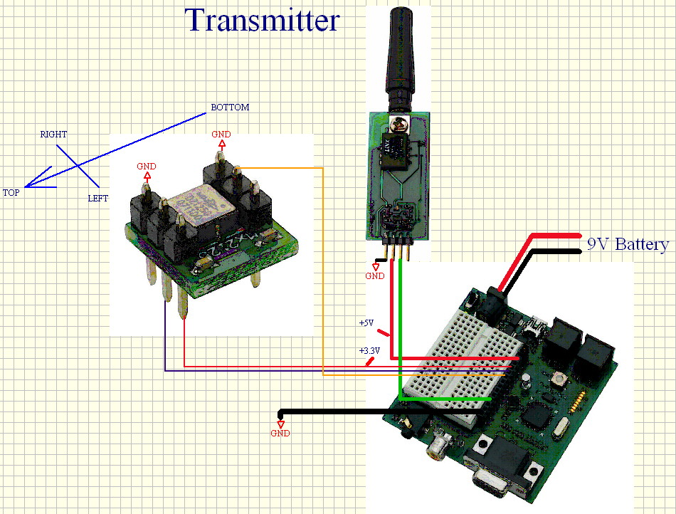
There is a 'safety' feature that I feel is important to implement on ALL wireless designs. The transmitter MUST be in constant communication with the receiver. If there is a 'glitch' due to environmental noise or out of range and the receiver can't recover within 1/4 of a second, the main power to the drive motors is shut down.
Also, the communication speed is 6000 baud ... this could be anything as long as the transmitter and receiver are set the same, but I wanted to choose an odd-ball number, so it would be less likely to receive valid code from another source if the transmitter was off or out of range.
Transmitter:
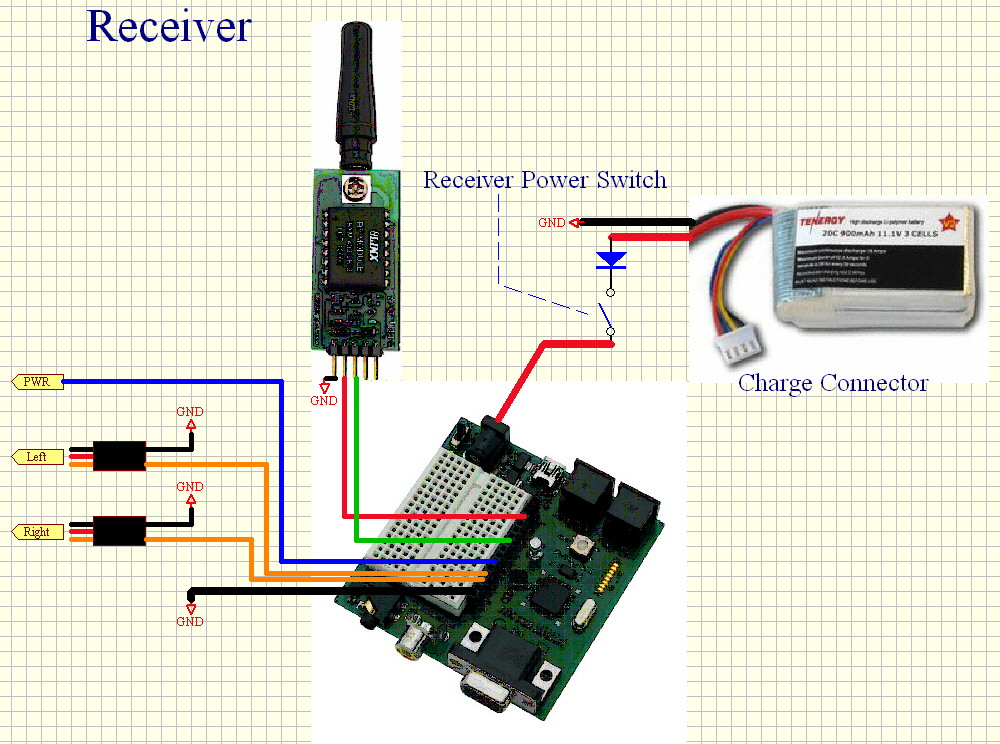
Receiver:
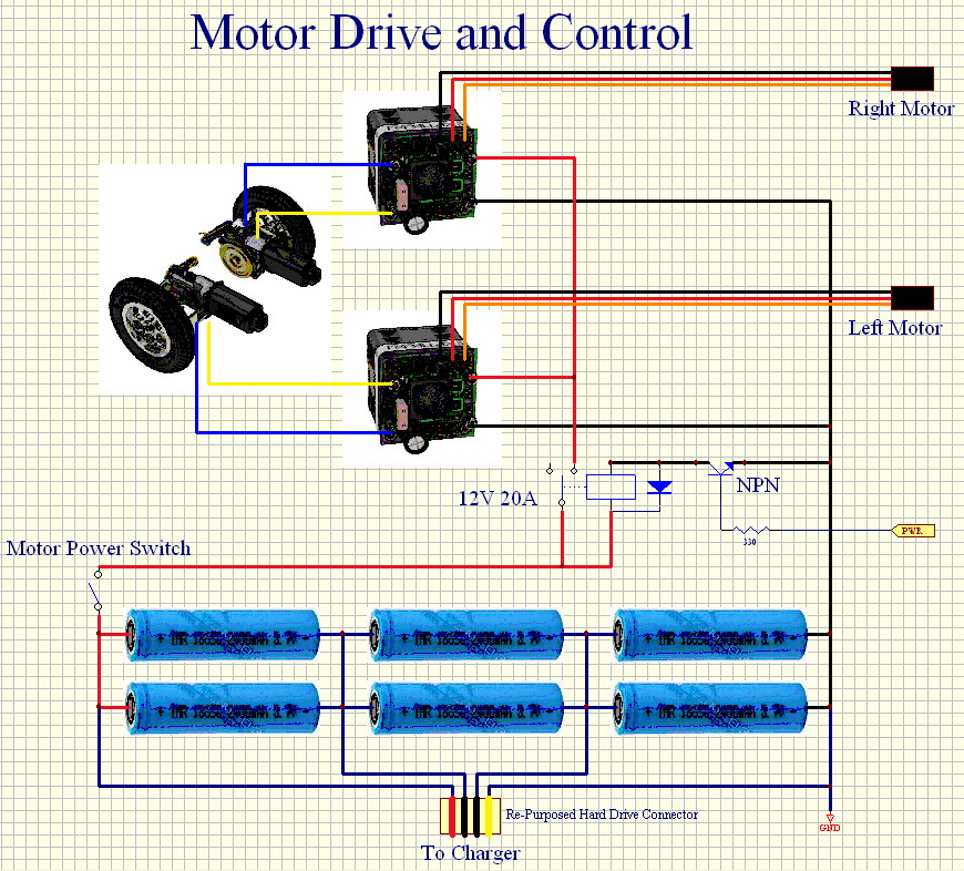
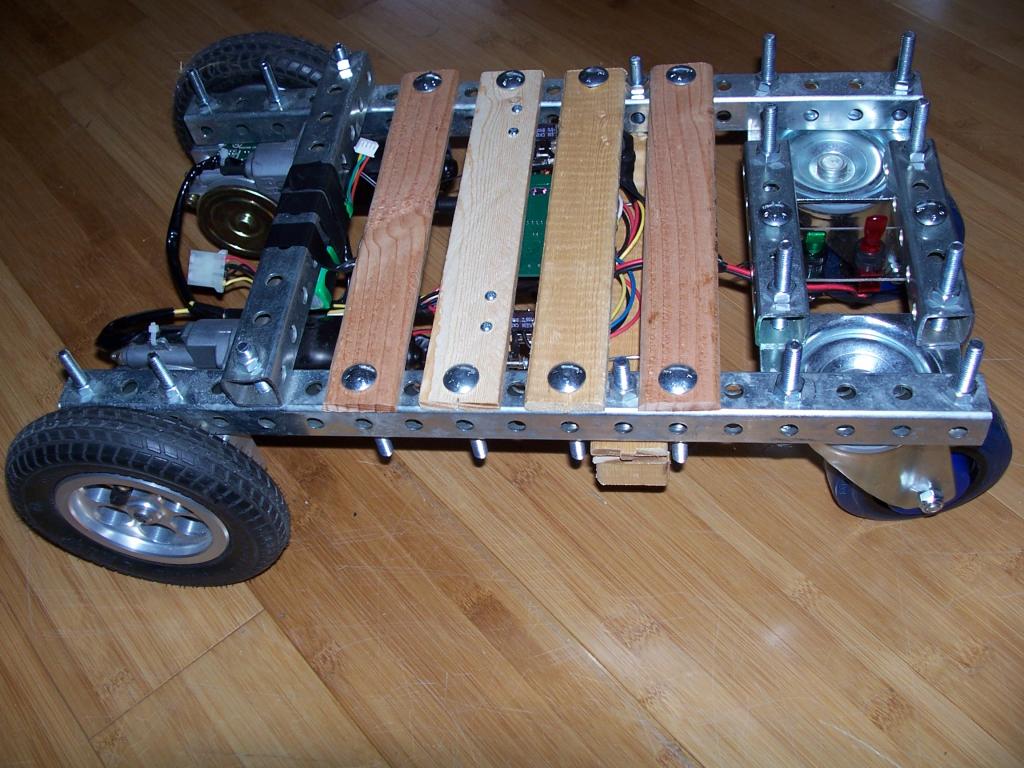
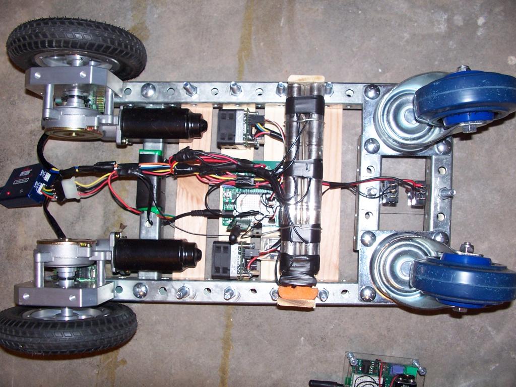
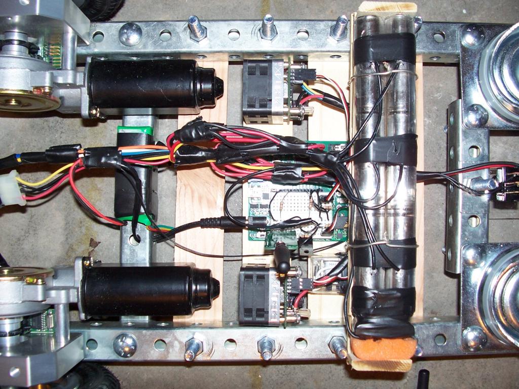
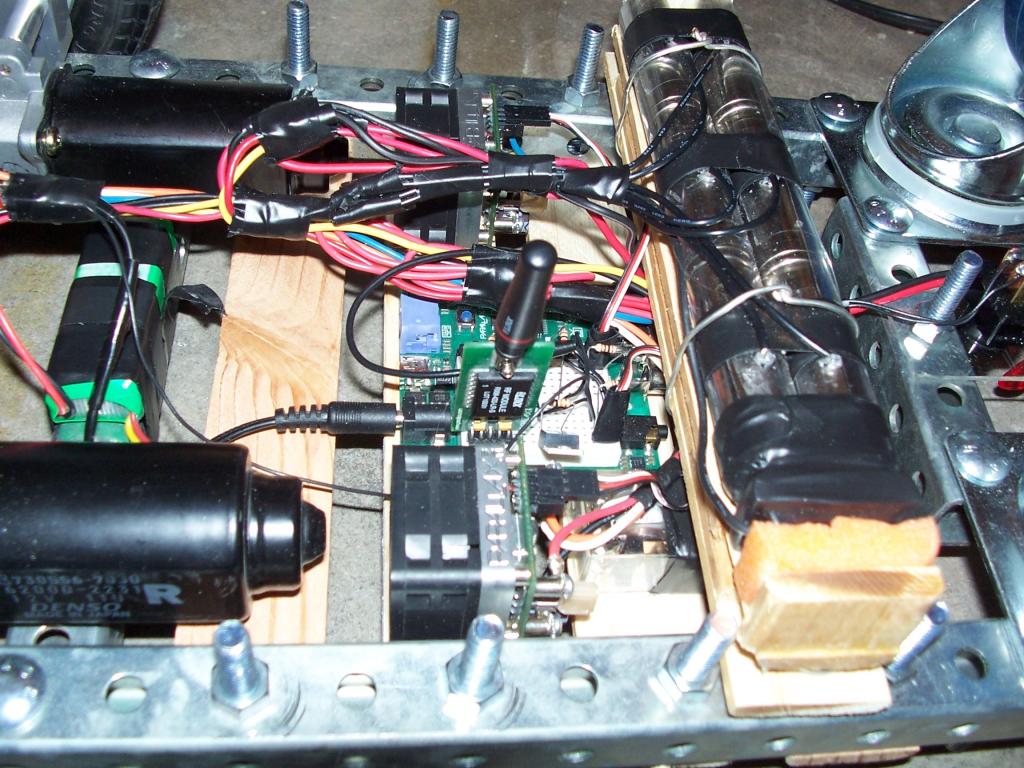
Undercarriage:


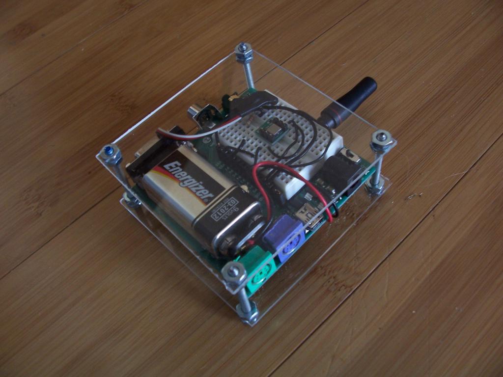
Receiver (Top):
Transmitter:
Propeller Code:
Attachment not found.
Attachment not found.
http://forums.parallax.com/showthread.php?118861-Homebuilt-Robotic-Platform-AKA-Retrobot&p=873514&viewfull=1#post873514
... and it sat, and sat. Last Monday My oldest daughter comes to me and says "Daddy, the show and tell topic for this week at school is inventions, and I want you to bring that robot that you made where GiGi (<- my youngest daughter) and I got to ride on it" ... Ok, so yeah, when I put the frame together in January I 'tapped' the motors to a battery with them sitting on it and made it go.
Anyway, I was looking for an excuse to put this thing together. I knew I had all the stuff laying around, but nothing put together. I spent spent 3 evenings working on code and hardware and was able to present it last Thursday in front of 30+ eight year olds. Needless to say it was a great success, and there were tons of questions. :-)
This really is a simple design, but I thought it would be a good start for someone else to work with to get them started.
There is a 'safety' feature that I feel is important to implement on ALL wireless designs. The transmitter MUST be in constant communication with the receiver. If there is a 'glitch' due to environmental noise or out of range and the receiver can't recover within 1/4 of a second, the main power to the drive motors is shut down.
Also, the communication speed is 6000 baud ... this could be anything as long as the transmitter and receiver are set the same, but I wanted to choose an odd-ball number, so it would be less likely to receive valid code from another source if the transmitter was off or out of range.
Transmitter:
Receiver:
Undercarriage:
Receiver (Top):
Transmitter:
Propeller Code:
Attachment not found.
Attachment not found.
950 x 722 - 252K

1000 x 744 - 266K

870 x 786 - 323K

1024 x 768 - 124K
1024 x 768 - 136K

1024 x 768 - 81K
1024 x 768 - 160K
1024 x 768 - 146K
Comments
Good Job on the Platform...I like that u used the odd baud for a built in failsafe.
Thank you for sharing this project! It is very helpful for my project too!
I would like to ask you if it is possible to replace one of the Propeller Demo Boards (the receiver or the tnansmitter) with a Basic Stamp Board and Bs2 microcontroller.
If it is possible which one is preferable to replace? The receiver or the transmitter? and finaly could you give us some examples for this (code and schematic)?
Nikos
I like it as well