Shop OBEX P1 Docs P2 Docs Learn Events
Please help me!!! — Parallax Forums

Please help me!!!

spacemanrenspacemanren Posts: 12
edited 2010-12-01 18:32 in Propeller 1
Hi,
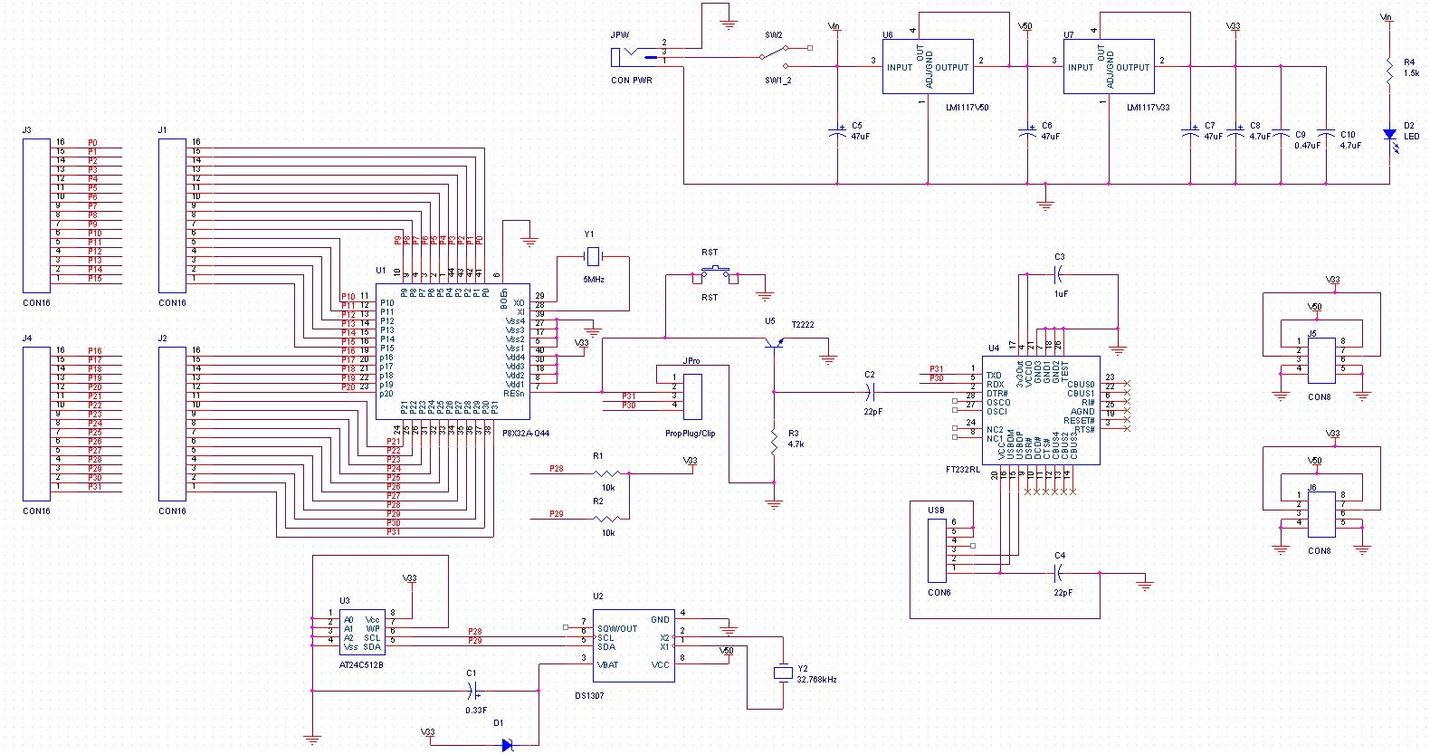
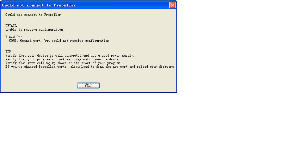
I am a chinese student. Recently, I found Propeller Chip is a good choice for my work. And I have made an Peopeller Platform USB board(P8X32A-Q44) by myself. I used the chip FT232RL. But when I welded the PCB board, it could not connect to the computer. The ViewPort says " Unable to receive configuration ". Then I followed the USBDriverTroubleshooting-V1.0's instructions to adjust my computer, but it also could not work.
Please help me!!! How can I solve the problem? I attach my Schematic diagram and the " could not connect to Propeller " Warning for your information.
Thank you very much!!! I'm looking forward to your reply.
1580 x 833 - 232K
960 x 540 - 36K

Comments

  • TonyWaiteTonyWaite Posts: 219
    edited 2010-11-27 06:15
    Hi Spacemanren,

    Your board is certainly ambitious: there's a lot going on!

    Have you actually placed *all* of the components, or only the *minimum* of them to establish basic functionality?

    When connected to a supply, was the 3V3 supply stable when measured with a meter?

    How much testing and checking did you do before power-up?

    A photo would be helpful to give us a few more clues regarding build-quality etc ...

    Regards,

    T o n y
  • spacemanrenspacemanren Posts: 12
    edited 2010-11-27 06:39
    I just use the software " Propeller Tool v1.2.5 " to test my board. And I choose the menu Run->identify hardware. It says Propeller chip version 1 found on COM3. Then I choose the menu Run->compile current->load ram. And it can work. But the software VeiwPort also can not connect my board. I do not know why. Could anyone tell me why?
    Thank you very much!!!
  • RaymanRayman Posts: 15,000
    edited 2010-11-27 06:51
    If the Prop tool is working with your board, then I'd say your hardware is fine and you just need to figure out how to configure Viewport...

    Although, you may want to see if your crystal and PLL are working right. I'd try running fullduplexserial and see if you can send characters to the Propeller Serial Terminal...
  • hover1hover1 Posts: 1,929
    edited 2010-11-27 07:58
    I just use the software " Propeller Tool v1.2.5 " to test my board. And I choose the menu Run->identify hardware. It says Propeller chip version 1 found on COM3. Then I choose the menu Run->compile current->load ram. And it can work. But the software VeiwPort also can not connect my board. I do not know why. Could anyone tell me why?
    Thank you very much!!!

    Make sure your Port selection is correct in Viewport. I use Ver 4.4.5, and I select Edit > Port Preferences. Make sure your Prop port is on top and selected, (COM 3: in your case).

    attachment.php?attachmentid=75755&d=1290873466


    Hope that helps,

    Jim
    599 x 467 - 106K
  • spacemanrenspacemanren Posts: 12
    edited 2010-11-27 08:58
    hover1 wrote: »
    Make sure your Port selection is correct in Viewport. I use Ver 4.4.5, and I select Edit > Port Preferences. Make sure your Prop port is on top and selected, (COM 3: in your case).

    attachment.php?attachmentid=75755&d=1290873466


    Hope that helps,

    Jim

    Thank for your help! I select Edit > Port Preferences, and my Prop port is on top and selected. Here is the picture. But it also could not connect to the computer. How to configure Viewport? Do I make some mistake?
    1.JPG
    567 x 560 - 69K
    1.JPG 68.9K
  • SapiehaSapieha Posts: 2,964
    edited 2010-11-27 08:58
    Hi spacemanren.


    First at all
    Download from Parallax new version of Propeller Tools 1.2.7 R2.

    Test with it and if it not function send picture of Mounted PCB (both sides)

    To see reliablity of Yours placement of BULK and decoupling's capacitors.


    I just use the software " Propeller Tool v1.2.5 " to test my board. And I choose the menu Run->identify hardware. It says Propeller chip version 1 found on COM3. Then I choose the menu Run->compile current->load ram. And it can work. But the software VeiwPort also can not connect my board. I do not know why. Could anyone tell me why?
    Thank you very much!!!
  • HannoHanno Posts: 1,130
    edited 2010-11-27 11:24
    Hi Spacemanren,
    Welcome to the Propeller- looks like you're in for a fun project!
    I'm the author of ViewPort. It may take a little bit of patience to get going with ViewPort- but I'm sure you'll succeed.

    First think I would try is: "Run/identify hardware" inside of ViewPort.
    Then, open "00-Debug" inside ViewPort and "Run/load ram".
    Let me know what happens with both of these.

    By the way- I've just uploaded a new beta:
    - integrates Michael Park's excellent HomeSpun compiler to support multiple libraries!
    - early support for BasicStamp2- edit with syntax highlighting, compile with Parallax's tokenizer, and identify/load to BasicStamp2.
    - improved interface- more room for editing/viewing

    I'll officially announce it later this week- still need to update the documentation and make some videos.
    Hanno
  • spacemanrenspacemanren Posts: 12
    edited 2010-11-27 18:27
    Hanno wrote: »
    Hi Spacemanren,
    Welcome to the Propeller- looks like you're in for a fun project!
    I'm the author of ViewPort. It may take a little bit of patience to get going with ViewPort- but I'm sure you'll succeed.

    First think I would try is: "Run/identify hardware" inside of ViewPort.
    Then, open "00-Debug" inside ViewPort and "Run/load ram".
    Let me know what happens with both of these.

    By the way- I've just uploaded a new beta:
    - integrates Michael Park's excellent HomeSpun compiler to support multiple libraries!
    - early support for BasicStamp2- edit with syntax highlighting, compile with Parallax's tokenizer, and identify/load to BasicStamp2.
    - improved interface- more room for editing/viewing

    I'll officially announce it later this week- still need to update the documentation and make some videos.
    Hanno

    Hi Hanno,
    First, thank you for your help! I followed your instructions. I select " Run/identify hardware ", and it says " found propeller chip on COM3 ". Then I open "00-Debug" inside ViewPort and "Run/load ram", and it also could not work. Here is the picture.
    655 x 472 - 64K
    1.JPG 64.1K
  • hover1hover1 Posts: 1,929
    edited 2010-11-27 18:32
    Hi Hanno,
    First, thank you for your help! I followed your instructions. I select " Run/identify hardware ", and it says " found propeller chip on COM3 ". Then I open "00-Debug" inside ViewPort and "Run/load ram", and it also could not work. Here is the picture.

    Do you have your Crystal installed securely? Is it 5 Mhz?

    Jim
  • spacemanrenspacemanren Posts: 12
    edited 2010-11-27 18:41
    hover1 wrote: »
    Do you have your Crystal installed securely? Is it 5 Mhz?

    Jim

    Hi Jim,

    Yes, it is 5MHz. And I have installed it. And could you tell me the way to make sure my Crystal installed securely or not? Thank you very much!
  • AribaAriba Posts: 2,690
    edited 2010-11-27 20:40
    Hi Spacemanren,

    has C2 really a value of 22pF or is this wrong in the schematic?
    This capacitor is normally 10nF, in your case with a 4.7k resistor 22nF would be better.
    The reset puls is very short with a 22pF C2 and this may result in unreliable detection of the propeller.

    Andy
  • HannoHanno Posts: 1,130
    edited 2010-11-27 23:31
    Hi,
    In order for ViewPort to communicate with your board all of the following have to be true:
    - Propeller gets enough power and doesn't brown out (use a good power supply)
    - Propeller is clocked properly (the programs that come with ViewPort are written for a 5MHz crystal)
    - Propeller is running a program which properly calls the vp.share object- ie, it doesn't use pins 30/31 for something else, it calls vp.share once at the beginning, it doesn't reset the Propeller.
    - Propeller is connected to the PC with a good connection (NOT the cheap retractable USB cables that Parallax gives out with the PropPlug)
    - ViewPort is able to find the Propeller

    Many people have had issues at this step- but so far everyone has ended up succeeding...
    Hanno
  • SapiehaSapieha Posts: 2,964
    edited 2010-11-28 05:03
    Hi spacemanren.

    Only time I get that error from ViewPort are If I have wrong _xinfreq else _clkmode activated in my program in conjunction to my Crystal.

    As You can see in example code I attach I test some of PCB's I have made Layouts to for speed reliability.

    BUT You even can have that issues even IF:

    You omitted decoupling's capacitors to PROPELLER / Have not enough of them ELSE have to small VOLTAGE-traces to Propeller and omitted BULK capacitor as near Propeller pins as possible.
    As in that cases You will have to BIG fluctuation on Voltage applied to Propeller.

    Omitted to apply Voltage/GND to all pins on Propeller that need them.
    (Every Voltage pin need it's own decoupling capacitor to)


    '           Function at all PROPELLER IC's
    '  _clkmode     = xtal1 + pll8x         'FOR 2x Crystals
       _clkmode     = xtal1 + pll16x     'FOR 1x Crystals
      _xinfreq        = 5_000_000          'use standard 5MHz clock Crystal   PLL 16x (without divider)
    '   _xinfreq        = 6_250_000         'use 6_250_000MHz clock Crystal    PLL 16x (without divider)
    '   _xinfreq        = 14_318_180        'use 14_318_180MHz clock Crystal   PLL 8x (with 1 stage divider)
    
    
    Hi Hanno,
    First, thank you for your help! I followed your instructions. I select " Run/identify hardware ", and it says " found propeller chip on COM3 ". Then I open "00-Debug" inside ViewPort and "Run/load ram", and it also could not work. Here is the picture.
  • spacemanrenspacemanren Posts: 12
    edited 2010-11-29 07:38
    I test my crystal,but there is no signal. It seems that the program does not run. But the software could identify the chip,and I can download program to the ram of the propeller chip. Does anyone could tell me why? Thank you!
  • StefanL38StefanL38 Posts: 2,292
    edited 2010-11-29 08:45
    the propeller-chip has an internal osccillator.
    If no chrystal is connected or defect the internal oscillator is used.

    This internal oscillator is not very accurate 8-12MHz.

    The protocol for identifiying the hardware is designed to work with even
    such a big frequency-deviation of the clock-signal.

    Serial protocols like PST.EXE or Viewport need the accuracy of a chrystal
    AND the systemconstants setup properly

    best regards

    Stefan
  • HannoHanno Posts: 1,130
    edited 2010-11-29 11:03
    Stefan is exactly right. To use the Propeller at it's designed frequency you need a working crystal. Identifying the chip just tells you the bare minimum is working. ViewPort pushes the limits beyond that...
    Hanno
  • spacemanrenspacemanren Posts: 12
    edited 2010-11-29 17:39
    Hanno wrote: »
    Stefan is exactly right. To use the Propeller at it's designed frequency you need a working crystal. Identifying the chip just tells you the bare minimum is working. ViewPort pushes the limits beyond that...
    Hanno

    The software Propeller-tool-v1.27 could identify my board,but ViewPort still could not connect to the board. I downloaded Exercise02-1 to my board by using Propeller-tool.
    But there was no signal that I can test on pin 16. I think the program uses the internal clock. Why is there no signal I can test on pin 16?
  • hover1hover1 Posts: 1,929
    edited 2010-11-29 18:01
    The software Propeller-tool-v1.27 could identify my board,but ViewPort still could not connect to the board. I downloaded Exercise02-1 to my board by using Propeller-tool.
    But there was no signal that I can test on pin 16. I think the program uses the internal clock. Why is there no signal I can test on pin 16?

    Could you post the code for "Exercise02-1". I'ts unclear where it came from. Is it from Viewport, PEKits, ?

    I almost sound like a PLL failure on the Propeller chip. If you can identify the Propeller, and download a program to the Propeller, but can not run the program, that is sometimes the symptom. The Propeller does not need a crystal, to be identified or download a program to RAM. It will need a operating oscillator/crystal (PLL) to be able to work with Viewport.

    In your initial schematics, you did not show if bypass capacitors where on ALL the Propeller power pins as Sapieha had questioned about. If proper bypassing is not done, it is known that this will lead to a PLL failure, and the crystal oscillator will not work and the Propeller will default to the internal 8-12Mhz clock, which will not work with Viewport.

    A picture of your board would also help.

    Jim
  • spacemanrenspacemanren Posts: 12
    edited 2010-11-29 18:13
    hover1 wrote: »
    Could you post the code for "Exercise02-1". I'ts unclear where it came from. Is it from Viewport, PEKits, ?

    I almost sound like a PLL failure on the Propeller chip. If you can identify the Propeller, and download a program to the Propeller, but can not run the program, that is sometimes the symptom. The Propeller does not need a crystal, to be identified or download a program to RAM. It will need a operating oscillator/crystal (PLL) to be able to work with Viewport.

    In your initial schematics, you did not show if bypass capacitors where on ALL the Propeller power pins as Sapieha had questioned about. If proper bypassing is not done, it is known that this will lead to a PLL failure, and the crystal oscillator will not work and the Propeller will default to the internal 8-12Mhz clock, which will not work with Viewport.

    A picture of your board would also help.

    Jim

    The program is from Propeller-tool. Here it is.
    PUB Toggle
    dira[16]~~
    repeat
    !outa[16]
    waitcnt(3_000_000+cnt)
  • hover1hover1 Posts: 1,929
    edited 2010-11-29 18:31
    The program is from Propeller-tool. Here it is.
    PUB Toggle
    dira[16]~~
    repeat
    !outa[16]
    waitcnt(3_000_000+cnt)

    That program should work without a CON statement for Xtal and frequency as long as it is in format:
    PUB Toggle
    dira[16]~~
     repeat
      !outa[16]
      waitcnt(3_000_000+cnt)
    

    with the correct indentation.
    PUB Toggle
    dira[16]~~
    repeat
    !outa[16]
    waitcnt(3_000_000+cnt)
    

    will not work.

    Can you test on another pin?

    Jim
  • spacemanrenspacemanren Posts: 12
    edited 2010-11-30 04:45
    hover1 wrote: »
    Could you post the code for "Exercise02-1". I'ts unclear where it came from. Is it from Viewport, PEKits, ?

    I almost sound like a PLL failure on the Propeller chip. If you can identify the Propeller, and download a program to the Propeller, but can not run the program, that is sometimes the symptom. The Propeller does not need a crystal, to be identified or download a program to RAM. It will need a operating oscillator/crystal (PLL) to be able to work with Viewport.

    In your initial schematics, you did not show if bypass capacitors where on ALL the Propeller power pins as Sapieha had questioned about. If proper bypassing is not done, it is known that this will lead to a PLL failure, and the crystal oscillator will not work and the Propeller will default to the internal 8-12Mhz clock, which will not work with Viewport.

    A picture of your board would also help.

    Jim

    Hi,
    Thank you for your help! Here are the pictures of PCB (both sides). Please help me to see the reliablity of my routing and decoupling's capacitors. I am a beginner. So I do not know where is the mistake. Thank you very much!
    1580 x 833 - 232K
    1854 x 878 - 190K
    1854 x 878 - 158K
  • SapiehaSapieha Posts: 2,964
    edited 2010-11-30 05:39
    Hi spacemanren.

    I have looked on Yours SCH/Layout.

    You have good on Bulk Capacitors (Some I maybe have placed in other places)

    And I think You not understand significance of decoupling capacitors.
    That capacitors need be about (10-100nF) and only Propeller IC nedd 4 of them (one betwen every VCC/GND pin) and all others IC's on Yours SCH need at last one of that.
    Even Regulators need some decoupling capacitors to.

    Before that it will be gambling to have this PCB to work.

    Hi,
    Thank you for your help! Here are the pictures of PCB (both sides). Please help me to see the reliablity of my routing and decoupling's capacitors. I am a beginner. So I do not know where is the mistake. Thank you very much!
  • spacemanrenspacemanren Posts: 12
    edited 2010-12-01 18:32
    Why my Propeller Tool v1.2.7 can identify the chip and download program to it. But the program does not run. The program is very easy and just use the chip's internal clock.
Sign In or Register to comment.