

Academic Analog Circuit Puzzle
 Beau Schwabe
Posts: 6,576
Beau Schwabe
Posts: 6,576
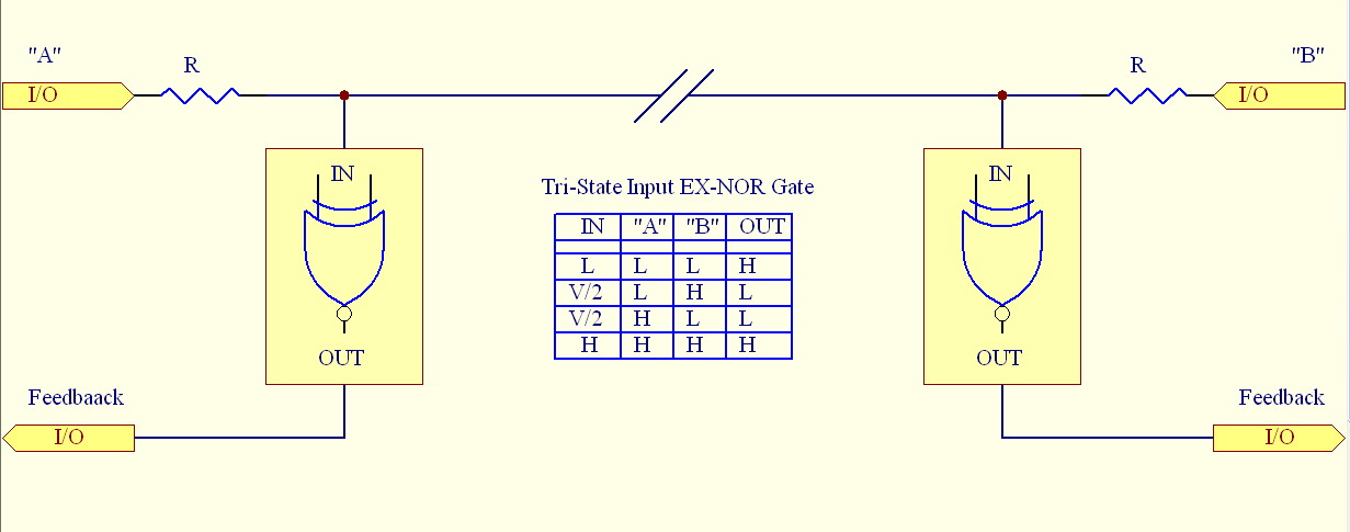
I was looking into MLT-3 signaling used in Ethernet communication, and stumbled across something that sparked an idea that I have had for simultaneous bi-directional communication for a long time. I fiddled around here and there and came up with an analog circuit using a few discrete components performing the correct decoding function needed to do this.
Anyway, the idea is, that data is transmitted on the "A" or "B" I/O and feedback on the other I/O determines if the 'opposite' side is in agreement or not. If they agree the Feedback signal is "high" otherwise the signal is "low".
I have a solution using 9 discrete components that I will post later, but I wanted to see what others would come up with.
1231 x 485 - 76K
Comments
I suspect one input of the XORs should be the actual value of the transmitted data (A or
The X-NOR has one Tri-state input that works on three different voltage levels (Low, V/2, and High)
If you look at the output of the X-NOR with respect to "A" and "B" through the resistor divider the output function is an X-NOR.
The "Feedback" signal is just so the system sending knows the state of the recipient. Assuming the system knows the signal that it is sending (High or Low), by looking at the Feedback, it can determine the state of the recipient.
So the challenge is to build that tri-level gate thing then.
"So the challenge is to build that tri-level gate thing then" - Yes, a window comparator essentially that is suppressed at Vdd/2, the resistors give it the X-NOR characteristics.
BTW) No Op-Amps allowed here.
6 components so far. No matter if the output polarity is up side down as we can invert it in software:)
Well... I have to start over, now! :-)
Bill
Only one LED can be on at a time, so we only need one current limiting resistor feedingh, down to to five components:)
If A<B, the top NPN will conduct, pulling /B low. If A>B, the PNP will conduct, pulling /B high. If A=B, neither conducts, so the bottom NPN biases /B to /A.
-Phil
http://mountains.ece.umn.edu/~sobelman/papers/mthsieh_iscas04.pdf
http://cva.stanford.edu/books/dig_sys_engr/lectures/l9.pdf
http://www.ee.ucla.edu/~ingrid/Publications/2002epep.pdf
Phil,
I'll have to simulate your design, but I think the B-C junction of the NPN and the PNP will form a back to back parallel diode regardless if the transistors are on or not.
I think it could also be done with MOSFETs if the signaling voltage was high enough.
-Phil
Two LEDs in parallel, opposite polarity.
Put this arrangement in series with R.
Use a photo transistor with resistor to positive supply to detect light from the LEDs
Junction between photo transistor and resistor is the feedback signal. A LED ON gives you a low on the feed back pin.
If you are transmitting a 1, one LED or other will be ON if the other end is transmitting a 0. Else it's OFF.
If you are transmitting a 0 one LED or other will be ON if the other end is transmitting a 1. Else it's off.
We have enough information here to decode what the other end is sending whatever state our end is in.
Put the same circuit at both ends.
Always assuming we can light two LEDs in series with the given drive voltage.
I think that will work. I know the objective was to do it with discrete components, but there are optoisolators that have front-to-back parallel LEDs built in: three components (2 resistors, 1 optoisolator).
-Phil
Does it have any possible advantage over using two wires?
Edit: Isn't that 2 components? The series resistor for the LEDs is already given as R.
-Phil
"Does it have any possible advantage over using two wires?" - One possibility, is that if you convert an existing infrastructure you suddenly have twice the throughput.
That beats mine by one component ...
Optimized for 3.3V operation:
3-NPN's
4-Resistors
2-Diodes
Actually you can reduce your version down to 6 components if you eliminate the NPN transistor and convert the PNP's to NPN's
From looking at the solutions, there seems to be two general ways way to do this:
1) Is to detect the polarity on the line
2) Is to detect Vdd/2 (a window comparator)
I'm not sure which is better over the other or if it should really matter, or is one is faster over the other.
Here is the version I came up with using the #2 comparator style.
The Window is targeted from 1.4V to 1.8V when supplied with 3.3V
All the AC optoisolators I am aware of are fairly slow so max speed would be around 9600 baud, maybe as high as 19.2K.
As to advantage over 2 wires, none, probably a speed disadvantage in most cases. The advantage comes if you are doing a retrofit or upgrade, need full duplex, and only have 1 free wire in an existing cable. A situation I have encountered several times in the past.
The resistor divider between Vdd and Vss sets a bias point for the feedback slightly above Vdd/2. When A is high, the MOSFET pulls the bias point slighlty below Vdd/2. That way, the voltage at the feedback point will be > Vdd/2 when B is high and < Vdd/2 when B is low, regardless of the state of A. (The divider resistors have to be large compared to R.)
-Phil
The schematic below is a derivative of what I was talking about with reducing your design down to 6 components.
Here is a 4.5 component design using the voltage detection option #1 I mentioned earlier (.5 - the resistor could be shared as one)