

Powering up your Spinneret without releasing the magic smoke.
 Oldbitcollector (Jeff)
Posts: 8,091
Oldbitcollector (Jeff)
Posts: 8,091
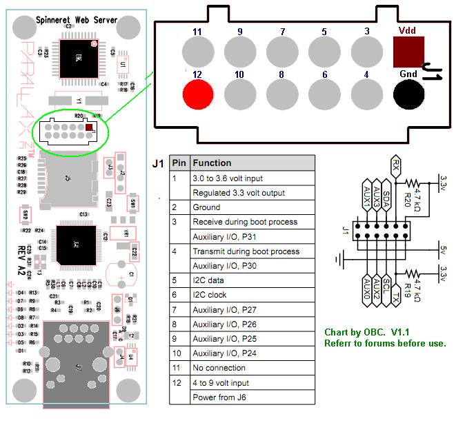
Ok, if a picture is worth a thousand words, perhaps this will keep me and others from letting the magic smoke out of our Spinneret boards. Could one of the experts (/me points at Phil ") ) take a look at this and verify it's correctness?
) take a look at this and verify it's correctness?
Edit: Updated attachment from comments here. It's correct now.
Thanks!
OBC
Edit: Updated attachment from comments here. It's correct now.
Thanks!
OBC
674 x 617 - 76K
Comments
But it doesn't exactly set the whole picture 100% here, and by the looks of things for a few others too.
Refer to my avatar and you'll understand completely.
OBC
We know that on J6 PIN R is Supply and PIN B is ground. Using a multimeter measure resistance between B/J6 and J1 either of the pins you think could be ground. The lowest resistance is the ground pin. This is the same test for R/J6 and 12/J1.
From myself measuring the resistance shows me that J1 is counted starting with PIN1 and then moving to the right for PIN 2. Now I still may be wrong but that is what the multimeter is telling me.
I've updated the original post with a new attachment. I *think* it's right now.
OBC
1. Both SCL and SDA are pulled up, too.
2. Pin 12, the one labeled 4-9V, should be a regulated +5V whenever a daughtercard is plugged in. This means that, when using a daughtercard, the power provided at J6 has to be +5V.
3. If you're not using another daughtercard, Parallax's PWR-I/O-DB daughterboard is a handy way to power the Spinneret from a wall transformer and to provide six powered servo-style 3-pin connectors. The catch is that all three pins on the right-hand side of its J3 header have to be connected together. This entails either two very-low-profile jumpers, wire-wrapping, etc., to pull off. Also the board provides no series resistance to the servo headers' signal pins, so you have to provide external current limiting for 5V logic coming into the the board. If I had this board to do over again, I would address both these issues. But it's still usable as-is with the workaround I mentioned and some common sense.
-Phil
I like the idea of using this board - I just received a few to use with my Spinnerets. The 3-pin headers are pretty useful.
I just wanted to note that the J3 header is a 2mm header (unlike the 0.1 inch header used for the 3-pin connections). If it were 0.1 inch, it would be pretty straightforward for me to build a 3-way plug since I have lots of 0.1 inch hardware around. 2mm makes it a little more difficult. I'll probably either solder the connections or remove the header altogether (I don't know if my wire-wrap tool will fit between the pins).
1. The low-profile jumpers I mentioned are these. They can be stacked, as shown here:
2. Get one of these header connectors and solder the pins together:
3. Solder a wire to the bottom of the board (shown in red below) and jumper as shown:
'Don't know why I didn't think of this when I laid out the board. D'oh! But the idea was that the motherboard would always have a +5V regulator of its own, which would be fed by the Vin connection. Then, along came the Propeller Backpack and Spinneret, neither of which had room for one. Oh, well. Next time!
-Phil
As usual your posts are very helpful. I was able to get 5V power from a previously unused MOBO PWR/IO #28301 board as shown - by referencing your schematic graphic at the top of this post.
Phil,
I will try your jumper so I can connect the two boards together directly - a better approach - thank you
Also, just an observation on idle operating temperature where the WIZnet W5100 chip stabilizes at around 49.0 c after 20 min (28 above ambient), the propeller idles at 27c - we should be alright as my XMOS XS1-G4 runs at 58c at max speed and seems ok.
thank you both.
/michael
I think if you disconnect the white wire from your cable, you can plug the female plug on the end directly into J6 (next to the ethernet jack) - you won't need the extra wires. Just check the contact order.
That's where I'm connecting my power now (until I mod the motherboard power board).
Good idea, I didn't notice that J6 matches the I/O headers on the PWR/IO daughterboard. These connectors also match.
Thank you for the info, appreciated.
/michael
The W5100 will draw more power and get much warmer when you don't have it connected to an Ethernet connection. If the W5100 cannot establish a connection, it will turn its output drivers up to 11 and keep trying. Once it establishes a connection it will determine the minimum power level needed to establish a robust connection and turn down the drivers.
David Carrier
Parallax inc.
I assume that means that if it's going over a longer cable or a lower quality cable it'll use more power and run hotter than if you have a short good cable, right?
Thats perfect! Looks like powering up the Spinneret from the servo head of a Propeller Protoboard would work fine here as well. Nice regulated 5 volts and I don't have to worry about the signal wire being connected.
OBC
This is good configuration info. As you mentioned, yes, I noticed a 20% drop in both temperature and corresponding power when connected to ethernet - normal levels. In my case I tested 5.0v and 7.5v from a bench supply into J6. I observed the following.
Without connected ethernet
0.19A @ 7.5V = 1.4W @ 51c
0.19A @ 5V = 0.95W @ 51c
With ethernet (50ft CAT6 to a Gigabit router)
0.16A @ 7.5V = 1.2W @ 42c
0.16A @ 5V = 0.8 @ 42c
As @Roy mentions, a lower drop would likely occur if I could use/stretch my 1ft cable long enough instead.
@OrbitCollector, thanks for the idea about power from the proto board.
..that reminded me that the mobo cards mount on the VGA connector holes on both the protoboards. I don't know if the fact that the holes match on the protoboard was intentional in the past but the Spinneret happens to mount exactly across the protoboard very nicely except that it will need larger standoffs to not block 3 of the 4 headers on the protoboard - here are some photos.
thank you
/michael
OBC, No problem, glad I could help. This sort of polarity determination occurs nearly daily by me and my staff at work when customers send us new products.
I don't have any of the mini pin connectors, but I discovered that if you take a standard snap-off connector of 5 pins, and remove the middle 3 pins, the two ends line up with each side of a 6 pin mini! (See Pics)
This may be common knowledge to many of you but it was a pleasant surprise to me
If this was done intentionally it's verycool and thoughtful.
So to solve my eventual plugging this thing in backwards, I decided to make it so I wouldn't have to remove the pins from the spinneret, and use a barrel connector, to a barrel connector which is fed by a 5V wall adapter. This way I can disconnect the power without taking out the pins out.
And now that the Prop Tool see's the Spinnerett, its time to code
Rick
It's an interesting idea, for sure. But, as I've cautioned before, the daughterboard socket is not designed to accept 0.025" square pins. (A 2mm header uses 0.020" pins.) It's possible to permanently spring the connector leaves by doing so, rendering the socket unreliable for use with daughterboards in the future.
-Phil
I'll have to get something a bit more proper, but this seemed better than sticking jumper wires into the socket
Like these from SparkFun (just a convenient link -- similar pins are available lots of places).