Shop OBEX P1 Docs P2 Docs Learn Events
Propeller Platform Logic Analyzer Module — Parallax Forums

Propeller Platform Logic Analyzer Module

jazzedjazzed Posts: 11,803
edited 2010-12-17 19:07 in Propeller 1
Hi. I'm looking for feedback on one of the projects I'm doing for the Propeller Platform to be sold at GadgetGangster.

If you've never used a logic analyzer for debugging, you don't know what you're missing.
Using a Logic Analyzer is like having millions of LEDs for debugging, but more practical :)
You can see signal changes over time and monitor codes output to pins from PASM for example.

Your feedback on hardware enhancements is welcomed as the board will not go to FAB for a week.


100MHz Logic Analyzer module feature set:
  1. Compatible with Propalyzer or ViewPort
  2. Compatible with any PC/Linux Program running serial data collection software
  3. Designed for 100MHz operation
  4. Allows monitoring up to 30 pins on the Propeller Platform or externally
  5. Requires a PropPlug for operation(1)
  6. Use without needing an extra power brick on Propeller Platform
  7. Can function as a battery powered (3 NiMh) stand-alone Propeller board
  8. Allows stacking boards for multi-Propeller experiments(2)
  9. Allows data collection with > 3.3VDC signals via series resistors
Notes:
  1. The PropPlug adds cost for using 1 board, but is cheaper/easier using multiple boards.
  2. A 1M Ohm pull-down is used and BOE can be pulled up for special reset control.
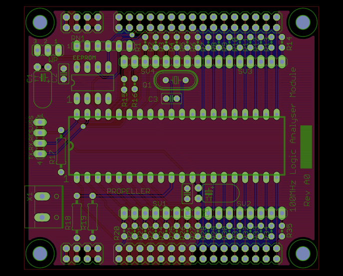
attachment.php?attachmentid=75291&stc=1&d=1289850433
687 x 553 - 249K
«1

Comments

  • Nick McClickNick McClick Posts: 1,003
    edited 2010-11-15 12:18
    Board looks very nice! You've done a great job with it. A few thoughts;
    1. You can always hide a few caps / resistors under the Prop if a socket is used.
    2. If I sell the kit, I can pre-program the EEPROM, if that's helpful...
    3. I like having a 2.8"x2.5" propeller through hole board - that's handy
    4. You could change the Xtal to a socket (just use 2 machined pins) so folks could use different speed crystals.
    5. Love the Write Protect jumper

    Where does X1 connect to? Is that for external power?
  • hinvhinv Posts: 1,255
    edited 2010-11-15 12:58
    Is this using the Propeller Platform so that we can debug what is attached to the propeller platform's signals, or as a replacement? I guess I don't know what the difference is besides the series resisters in a handy format. What kind of pricepoint were you thinking? Can I stack multiple propeller platforms now?
    Are you secretly trying to pushed a stacked multi-propeller computer without actually attracting suspicion? I think I'm on to you! ;^)

    Doug
  • Bill HenningBill Henning Posts: 6,445
    edited 2010-11-15 13:14
    Nice, looks extremely useful for the Propeller Platform.
  • jazzedjazzed Posts: 11,803
    edited 2010-11-15 13:16
    hinv wrote: »
    I think I'm on to you! ;^)

    Just call it multi-purpose :)

    I've used a Propeller for debugging projects for a couple of years now and find it very valuable. I found that having to use another brick with a stacked Propeller platform board very annoying, so I decided we needed a board that could just use the already regulated voltages. That with the ease of connecting to a powerful development platform made me think this is a reasonable idea.

    @Nick, yes X1 is a power connector for hooking up a 3AA NiMh battery pack.
  • schillschill Posts: 741
    edited 2010-11-15 14:00
    Are all of the on-board prop pins connected directly to the "riser" headers? If they can be isolated, then you could mix looking at signals from the stacked boards and external sources (i.e., some of the logic analyzer inputs could come from the stack and others from another board).
  • Cluso99Cluso99 Posts: 18,069
    edited 2010-11-15 15:01
    Steve, I am now using a mini-USB-AB to power and communicate with the PC. Of course code not complete. The PropPlug connection is only provided as an alternative connector. The mini-USB-AB will connect to the pc via most camera/phone cables. If you are interested, PM me.
  • Ding-BattyDing-Batty Posts: 302
    edited 2010-11-15 15:59
    Steve, what's the sample depth at 100MHz?

    I assume you are familiar with the Open Workbench Logic Sniffer, which is just under US$45. It samples up to 32 channels (16 buffered up to 5 V), at up to 200 MHz, and has a sample depth of 24K 8-channel samples (fewer for more channels -- limited RAM on the board). I have just started using it for some signal timing tests on one project.
  • jazzedjazzed Posts: 11,803
    edited 2010-11-15 18:02
    Cluso99 wrote: »
    Steve, I am now using a mini-USB-AB to power and communicate with the PC.
    @Cluso99, That would be a nice option, and I have room, but I don't plan to add a regulator. I've often thought about using 2 large diodes end to end to get down from 5V to 3.6V (upper end of the normal operating range). I'm concerned about the non-linear effects of using diodes though.

    @DingBatty, the sample depth at 100MHz I use today is about 500 x 32 bits. I know this can be higher (20KB+) by using a 5 COG solution as outlined by Kuroneko etal, but I've been too lazy to bother.

    This product is designed for Propeller enthusiasts using the Propeller Platform footprint.

    @schill, I've taken up your exellent suggestion to make sure that the card edge pins can be disconnected from Propeller and the series resistor protected connectors. I don't have room for 2 pin headers, but simple cuts/jumps can be made to achieve your goal.

    Here is the latest layout. It says A1, but there may be some changes before FAB.

    attachment.php?attachmentid=75324&stc=1&d=1289872778

    @hinv, I'm definitely not looking to replace any of the Propeller Platform boards. They have very hefty and useful voltage regulators - with lots of warm and fuzzy LEDs. No, I don't have room for LEDs on each pin so don't ask :)
    624 x 460 - 223K
  • Brian RileyBrian Riley Posts: 626
    edited 2010-11-15 21:21
    Great .... I will probably buy a dozen boards to start and add the full kit to my product line here. At least two of those boards will go on the bench here.

    The great thing about this is it eliminates the need/expense for an expensive (if you want it to last and be reliable) interface harness. Its like a BSLA for Propeller Platform.
  • schillschill Posts: 741
    edited 2010-11-16 05:56
    Its like a BSLA for Propeller Platform.
    That's the thought that came to my mind as well.
  • Cluso99Cluso99 Posts: 18,069
    edited 2010-11-16 06:30
    Steve, you could use a SOT23 regulator or a 1.8V zener in series as you are not using a lot of power for the prop.

    I note you only have 500 samples. I did about ~1700 samples using 4 cogs which you will need to do to get 100MHz sampling. It would not be too difficult to use all 8 cogs and get ~3000 32bit samples. The one thing I wanted to do was to perform sampling continuously so that I could effectively sample part way before the trigger. Haven't quite worked out how to keep the cogs rolling. However, at 25MHz it is doable. In fact, at 25MHz it is most likely possible to use hub as well.
  • Nick McClickNick McClick Posts: 1,003
    edited 2010-11-16 10:31
    That's the nice thing about using a Prop for this, you have the flexibility of using it as a DLA, a mix, or for something else completely.

    @Cluso - I think the idea is to keep it through hole, but having an option for a small SOT23 Vreg would be nice. What about just having pads for one on the bottom of the board and pads for a few SMT bypass caps? That way advanced users could add one on themselves.
  • jazzedjazzed Posts: 11,803
    edited 2010-11-16 11:11
    Thanks Brian. I'll build PCBs soon that are very similar to the Rev A1 shown.
    Great .... I will probably buy a dozen boards to start and add the full kit to my product line here. At least two of those boards will go on the bench here.

    The great thing about this is it eliminates the need/expense for an expensive (if you want it to last and be reliable) interface harness. Its like a BSLA for Propeller Platform.

    I'm also considering a more risky separate version that adds the USB connector as a serial port (update would not be using Propeller Tool). This option would eliminate the need for PropPlug for normal use, but would require PropPlug for programming. I've done it before successfully with BradC's USB peripheral code. The trick is to use prop-plug for initial programming and USB for communications and updates thereafter. This board is similar to what Nick mentions except that the SMD parts are on top.

    I'm planning an order of 9 pin header SMD grabber cables. Up to 4 of these cables could be used per board as required.


    @Cluso99, On the topic of samples, I use a version of your data-logger with your copyright below. Like I mentioned before, I believe I can arrange for a capture directly to hub which would greatly simplify the code and may allow "save to trigger" using a FIFO. The HUB buffer space would obviously be split by the number of cogs doing data collection.
    This program builds on work done in or by the following:
      Data Logger Demo v0.050                                                 
      Author: Ray Rodrick                                                     
      Copyright (c) 2008 Ray Rodrick                                          
      See end of file for terms of use.                                       
      Ray's Acknowledgement: to Paul Baker's Logic Analyzer (dscope.spin) for the   
      inspiration and naming conventions.                                     
    
  • jazzedjazzed Posts: 11,803
    edited 2010-11-16 12:34
    Here's the USB version.

    attachment.php?attachmentid=75364&stc=1&d=1289964172

    Updated: this one has LEDs for serial port activity.
    687 x 460 - 258K
  • UnsoundcodeUnsoundcode Posts: 1,532
    edited 2010-11-16 17:44
    Hello Jazzed , do you have available the protocol you are using for the PC serial data collection. I like the look of the project , I think it will do well. From my point of view USB is preferable to a Prop plug , thats an opinion not criticism.

    Jeff T.
  • Cluso99Cluso99 Posts: 18,069
    edited 2010-11-16 19:09
    Nick: The sot23 reg is quite easy to solder. It is only the 6 pin versions that become difficult. The caps can still be throughhole and 0.1" to save space if required.

    Steve: The attachment for the USB is not shoing up on your post (just an "x")

    Unsoundcode: I am pressing (or doing) a mini-USB-AB and expect we will not require any FTDI chip shortly. So we will have that avantage soon. I emailed Steve some more info. My circuit is here http://forums.parallax.com/showthread.php?t=126479&highlight=modblade+cluso99
  • jazzedjazzed Posts: 11,803
    edited 2010-11-16 19:55
    @Cluso99, I was updating the pic. Hope you can see it now.

    BTW, I put the SOT223 regulator over the 0.1 header so that they can not be used at the same time. I don't know yet, but I may change that - in retrospect, It's probably better just to have a 3 pin jumper. There are LEDs on the board to detect USB activity; there is some risk of interference with the USB signals, but I think it will be fine.

    @Unsoundcode, I understand the desire to use USB. I think it is valuable for users in many conditions. It should be pretty easy for example to offer a stand-alone version of this board in a nice case with some dimension changes.

    The USB version I posted will allow for USB and PropPlug though not simultaneously. I've used BradC's USB serial driver with Propeller several times and am happy with it. The USB driver will run in the Propeller - a Propeller Tool compatible bootloader would be ideal.

    Weening ourselves from FTDI chips and drivers is a valuable and achievable goal.

    The protocol I use with Propalyzer is simple. I expect to add commands as necessary to support commands like "save until trigger" some day so the protocol is subject to change. Of course there is nothing to stop you from defining your own protocol and capture code except not having a PropPlug for the time being.
    {{
      User Command Line Interface:
      All commands line end with enter character $d
      When a command is complete the "OK>" prompt will be sent.
      
      m x = set mask with hex value
      a x = set arm with hex value
      t x = set trigger with hex value
      p n = set sample period with a natural integer
      s n = set scale with a natural integer as defined in scaleString
      h n = set delay ... not implemented in gui
      c   = start capture
      d   = display parameters 
    }}
    
  • Cluso99Cluso99 Posts: 18,069
    edited 2010-11-16 20:37
    Nice Steve.

    I am pleased you have used Brads USB code. The FTDI chip at ~$4 is a bit steep when the prop is ~$8. I just have not had any software time in the last 6 months :-(

    A suggestion. Bill & I are using pluggable xtals using pins from Future Electronics. They need a larger hole though. If you have plenty of bypassing it will most likely run happily at 108MHz using 13.5MHz xtals. In fact it seems like the DIP Prop can actually run faster than the QFP. Sapieha has been running at 120MHz on TriBlade.

    PS. Thanks for the recognition in the code :)
  • SapiehaSapieha Posts: 2,964
    edited 2010-11-16 20:44
    Hi Cluso.

    Now as I have much more DIP Props I tested more extensively ADN --
    It is only some of them that can run with 15MHz PLL8x
    BUT all run with 14.318180MHz PLL8x

    Cluso99 wrote: »
    Nice Steve.

    I am pleased you have used Brads USB code. The FTDI chip at ~$4 is a bit steep when the prop is ~$8. I just have not had any software time in the last 6 months :-(

    A suggestion. Bill & I are using pluggable xtals using pins from Future Electronics. They need a larger hole though. If you have plenty of bypassing it will most likely run happily at 108MHz using 13.5MHz xtals. In fact it seems like the DIP Prop can actually run faster than the QFP. Sapieha has been running at 120MHz on TriBlade.

    PS. Thanks for the recognition in the code :)
  • Brian RileyBrian Riley Posts: 626
    edited 2010-11-16 21:02
    jazzed wrote: »
    Thanks Brian. I'll build PCBs soon that are very similar to the Rev A1 shown.


    I'm also considering a more risky separate version that adds the USB connector as a serial port (update would not be using Propeller Tool). This option would eliminate the need for PropPlug for normal use, but would require PropPlug for programming.

    That's good ... I have no interest in a USB version. The Prop Plug is not an issue, I sell an FTDI based board called "the BUB" for $14 that was designed as an Arduino programmer, it can (by a jumper) be set for 3 or 5 volts and with the addition of a $2 adapter board (to rearrange pinouts) it is an exact substitute for a Prop Plug. Further, if you have either an RS232 port or a USB-RS232 adapter, I have my "P1" serial adapter which I sell for $5 ($4 when bought with anything else) That could be used also, if you would add a fifth pin next to RX with 3.3 volts on it, as Nick did in some of his stuff and several others have proposed for use with the SerPLug.
  • jazzedjazzed Posts: 11,803
    edited 2010-11-17 08:53
    Further, if you have either an RS232 port or a USB-RS232 adapter, I have my "P1" serial adapter which I sell for $5 ($4 when bought with anything else) That could be used also, if you would add a fifth pin next to RX with 3.3 volts on it, as Nick did in some of his stuff and several others have proposed for use with the SerPLug.

    Added 3.3V to the PropPlug connector on the through-hole board. Let me know if there is anything else you would like. I'll probably FAB 20 boards.

    attachment.php?attachmentid=75409&stc=1&d=1290016592
    687 x 460 - 248K
  • Brian RileyBrian Riley Posts: 626
    edited 2010-11-17 21:26
    :smilewinkgrin: Great ... tnx for the consideration ... count me in for 12 and give me an idea what you think that will cost me. Have you a schematic for the board yet?
  • jazzedjazzed Posts: 11,803
    edited 2010-11-18 21:23
    :smilewinkgrin: Great ... tnx for the consideration ... count me in for 12 and give me an idea what you think that will cost me. Have you a schematic for the board yet?
    I always have a schematic before layout. I'm not sure about board pricing at this point. I'll contact you on PM.
  • schillschill Posts: 741
    edited 2010-11-19 05:23
    Dependent on cost, I'd also be interested in a couple boards.
  • David BetzDavid Betz Posts: 14,516
    edited 2010-11-19 06:40
    This sounds like yet another reason for me to get a Propeller Platform board. I'd like one of these logic analyzer boards too when they become available.
  • jazzedjazzed Posts: 11,803
    edited 2010-11-19 22:14
    I have better ideas for pricing the Logic Analyzer PCB today, but I think I'll do a 20 board FAB run before deciding on a price range. The FAB run should be about 2 weeks if everything goes smoothly. Thanks for your patience.
  • David BetzDavid Betz Posts: 14,516
    edited 2010-12-06 18:22
    Any update on the logic analyzer boards?
  • jazzedjazzed Posts: 11,803
    edited 2010-12-06 20:10
    David Betz wrote: »
    Any update on the logic analyzer boards?
    I've been very busy with several things, so progress has slowed a bit.

    Brian and I have been discussing more of what he wants his board to do
    and the design has changed accordingly. His board will be different from
    the USB board in several ways. The design should be ready to turn tomorrow.

    The USB board has had one change. I expect to start FAB on these two
    board designs and one or two others at the same time.

    Merry Christmas.
    --Steve
  • David BetzDavid Betz Posts: 14,516
    edited 2010-12-07 10:17
    I know this is intended as a logic analyzer but could I stack several of these on top of a Propeller Platform board and use them as attached processors to the main Propeller on the PP? In other words, could I use the connections between the boards to implement some sort of interconnection mechanism to allow the Propeller chips on the logic analyzer boards to act as a multi-propeller parallel processor? Or would the logic analyzer boards interfere with each other?
  • jazzedjazzed Posts: 11,803
    edited 2010-12-07 12:15
    David Betz wrote: »
    I know this is intended as a logic analyzer but could I stack several of these on top of a Propeller Platform board and use them as attached processors to the main Propeller on the PP? In other words, could I use the connections between the boards to implement some sort of interconnection mechanism to allow the Propeller chips on the logic analyzer boards to act as a multi-propeller parallel processor?
    Yes. That's why the resistors are connected to the BOE* and RST* pins.
Sign In or Register to comment.