

BS2 Control Relay - Question
 alyaros
Posts: 9
alyaros
Posts: 9
Hi All
I'm trying to build a relay circuit that is controlled by Basic Stamp 2.
My problem:
I know how to build the relay circuit but i don't know how to control it by the basic stamp.
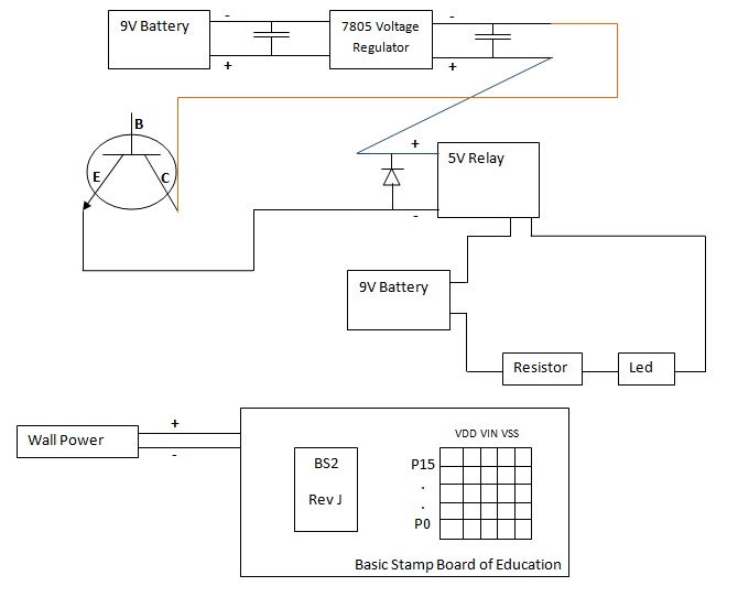
I attached an image file explaining what i have built so far.
my question is how to connect the Basic Stamp I\O Pin to the transistor Base Pin in order that it will activate the relay?
(Note that if i remove the transistor and connect the E And the B manually the relay works.)
but when i'm trying to add a transistor that will be controlled by the basic stamp - by connecting Pin 0 to the B (Base) the relay doesn't work.
i will appreciate your help,
Thanks
I'm trying to build a relay circuit that is controlled by Basic Stamp 2.
My problem:
I know how to build the relay circuit but i don't know how to control it by the basic stamp.
I attached an image file explaining what i have built so far.
my question is how to connect the Basic Stamp I\O Pin to the transistor Base Pin in order that it will activate the relay?
(Note that if i remove the transistor and connect the E And the B manually the relay works.)
but when i'm trying to add a transistor that will be controlled by the basic stamp - by connecting Pin 0 to the B (Base) the relay doesn't work.
i will appreciate your help,
Thanks
670 x 542 - 48K
Comments
http://www.parallax.com/Portals/0/Downloads/docs/cols/nv/vol1/col/nv6.pdf
Robert
The only hitch I can think of is -- if the transistor is a big one, and needs a hefty base current to saturate it, then the Stamp pin may not have enough current to drive it. What kind of transistor is it?
Back-Fly diode = 1N4005
Relay 5V \ 250VAC, 8A
The basic stamp program was:
DO
HIGH 0
LOOP
it doesn't work - the relay doesn't turn on.
Maybe it is because the Stamp and the Relay are working with different Power sources?
The connections are correct - i tested the circuit without the transistor - just bypassed it by connection E TO C and it worked.
Here's a test -- you said "manually" connecting the base worked? If tie the base of the transistor directly to 5v through a 470 resistor does it work? If it DOES then, perhaps your Stamp pin is bad. If it doesn't work, then something else is going on.
Here is code that would turn the relay on and off every two seconds:
i read it , this is what i was trying to do.
but it doesn't work - i assume i'm missing something...
but i don't know what..
can you explain?
how to tie all the ground together?
I Connected The Transistor Base to Pin 0 with a resistor.
Pin 0 is constantly HIGH. (The pin is OK i can turn on a Other Test led using it)
It Still Doesn't Work.
I have 2 Power Sources (MARKED Green) in my circuit.
Shouldn't they be connected some how??
i am one step far from activating this circuit -
i only need little Help :-)
(like in Mike2545's drawing)
Should I connect the relay regulated GND to the basic stamp
Regulated ground meaning the vss or to the GND cable that is coming from the wall transformar? Before the board of eductaiom voltage regulator ?
Or it doesn't matter because they are all the same Gnd ?
(pin 0 is stuck on High state - It's last state and i'm unable to program it to low
meaning Low 0 doesn't affect the pin)
but anyway, as soon as i get new Ones (Transistor at least) i will try to activate this circuit again.
Thanks for you advice
I think now my circuit will work.