

Wake Turbulence Countdown Timer
 WebheadFred
Posts: 27
WebheadFred
Posts: 27
Greetings everyone.
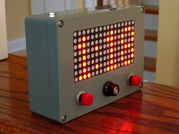
Thank you for taking the time to look at my first completed project. I am a watch supervisor in an air traffic control facility. One of the controllers issues is to provide adequate spacing between successive departures. Depending on the size, this could be 6000' and airborne for same-size small aircraft or up to three minutes for small aircraft behind a heavy.
One thing I am constantly looking for, is that the controller look out the window. It seems like a natural thing to do but documentation, and logging requires a lot of 'heads-down' time. I thought if I could minimize this by making a timer, the controllers wouldn't need to note the current time on a piece of paper, and continue to refer to that and look at the UTC clock. A timer seemed perfect.
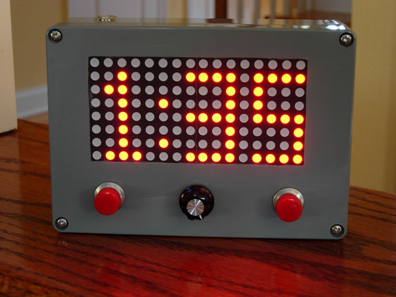
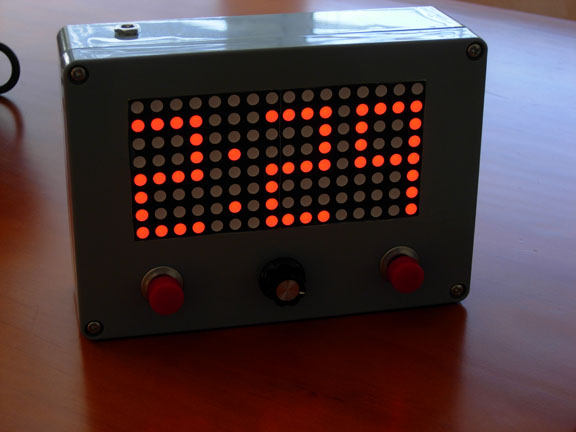
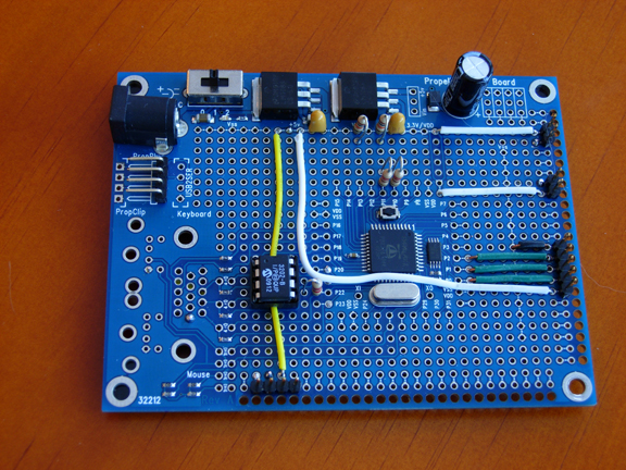
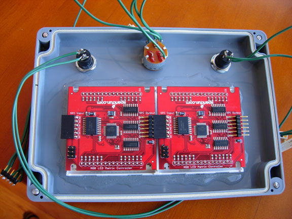
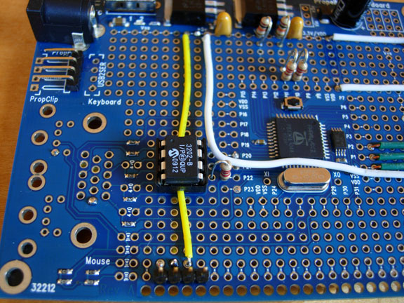
My project takes a Propeller proto board and two SparkFun RGB LED matrix with the SPI interface. I am reading a 10K potentiometer with an MCP3208 ADC and allowing the controller to select their desired color. It all runs on a 9 volt lithium battery with a plug-in back up.
In programming all this, I knew nothing about SPI interfaces and really only have ever just blinked LED's. I wanted to learn a little about the Propeller and get a handle on doing some cool stuff.
In programming the SPI-SparkFun array, I came across an interesting problem. According to the SparkFun documentation, I can send a '%' to the matrix. This places the array into command mode. The next number between 0 and 9, tells the array that there are more than one connected. As I was experimenting, I sent random colors to the display and admired my SPI routine. Cool I thought. Then it happened. The color %00100101 happened to be the '%' command. Of course if the next byte sent was the suitable number, the whole matrix would get out of whack and I'd have to reprogram them. The command would write to the flash and the change would be permanent. I though I was destroying the display.
As it turned out, I discovered the issue. I downloaded the source code and rewrote the C program eliminating the 'command' mode for my units. I re-flashed the unit with the new code, and set permanently the flash to my 2 connected chips. It worked perfectly.
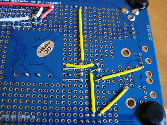
I'm reading a POT with the MCP3208 which is probably overkill, but I thought it would get my feet wet and provide useful info for other projects. Attached are photos and a YouTube video of the unit in action. The source code is yours for the use. Hopefully someone new to the prop can look at my code and get a little help on interfacing to these chips.
Thanks go to all of you out there too as I lurked through the forums and read with great interest, your problems and solutions. This is truly a great group.
Best Regards,
Fred
http://www.youtube.com/watch?v=f4Kbtr5KX3A
Thank you for taking the time to look at my first completed project. I am a watch supervisor in an air traffic control facility. One of the controllers issues is to provide adequate spacing between successive departures. Depending on the size, this could be 6000' and airborne for same-size small aircraft or up to three minutes for small aircraft behind a heavy.
One thing I am constantly looking for, is that the controller look out the window. It seems like a natural thing to do but documentation, and logging requires a lot of 'heads-down' time. I thought if I could minimize this by making a timer, the controllers wouldn't need to note the current time on a piece of paper, and continue to refer to that and look at the UTC clock. A timer seemed perfect.
My project takes a Propeller proto board and two SparkFun RGB LED matrix with the SPI interface. I am reading a 10K potentiometer with an MCP3208 ADC and allowing the controller to select their desired color. It all runs on a 9 volt lithium battery with a plug-in back up.
In programming all this, I knew nothing about SPI interfaces and really only have ever just blinked LED's. I wanted to learn a little about the Propeller and get a handle on doing some cool stuff.
In programming the SPI-SparkFun array, I came across an interesting problem. According to the SparkFun documentation, I can send a '%' to the matrix. This places the array into command mode. The next number between 0 and 9, tells the array that there are more than one connected. As I was experimenting, I sent random colors to the display and admired my SPI routine. Cool I thought. Then it happened. The color %00100101 happened to be the '%' command. Of course if the next byte sent was the suitable number, the whole matrix would get out of whack and I'd have to reprogram them. The command would write to the flash and the change would be permanent. I though I was destroying the display.
As it turned out, I discovered the issue. I downloaded the source code and rewrote the C program eliminating the 'command' mode for my units. I re-flashed the unit with the new code, and set permanently the flash to my 2 connected chips. It worked perfectly.
I'm reading a POT with the MCP3208 which is probably overkill, but I thought it would get my feet wet and provide useful info for other projects. Attached are photos and a YouTube video of the unit in action. The source code is yours for the use. Hopefully someone new to the prop can look at my code and get a little help on interfacing to these chips.
Thanks go to all of you out there too as I lurked through the forums and read with great interest, your problems and solutions. This is truly a great group.
Best Regards,
Fred
CON
_CLKMODE = XTAL1 + pll16x 'House Keeping setting up the Clock
_XINFREQ = 5_000_000 'and Processor speed.
BLUE = %00000011 'A few definitions for the color
GREEN = %00011100 'bits 7,6,5 define red and various intensities
RED = %11100000 '4,3,2 defines green and 1,0 defines blue.
black = %00000000
_cs = 1 'output pins for the SparkFun RGB array.
_clk = 0
_mosi = 2
in = 0 'arbitrary definitions. I think I use these somewhere
out = 1
_inv_high = 0 'These are for the hex inverters I used to flash an LED.
_inv_low = 1 'I placed these at various places to test if my code made it this
'far. In the final version, they are not used.
{{ 'these were used for DIP switches.
_switch1 = 19 'I decided not to use them for the color select as it was too
_switch8 = 26 'hands on and I wanted a much cleaner selection method
_dim = 27 'without giving the user too many choices.
}}
'so I decided on an 3202-B ADC and mapping it to 16 colors.
_ADC_cs = 20 'these are the pins for those communication lines.
_ADC_clk = 21
_ADC_in = 22
_ADC_out = 23
delay = 200000 'artifact. I used this at several places to determine timing for the SPI. As it turns out, I didn't need it.
_frame_size = 128 'this is the frame size I used. 2x64 for the LED array.
_const = 10
_debug = 15 'HEX inverter output pin for debugging purposes
foreground = red 'thought I'd put these here for flexibility.
background = black
_button2 = 10 '2 minute button
_button3 = 11 '3 Minute button
VAR
byte array[_frame_size] 'various counters and incrementers. I'm sure there is a more
byte idx 'efficient way of accomplishing this. I suppose it's a throwback
byte bit 'from my early programming days. Oh well.
byte time
byte minutes
byte offset1
byte offset2
byte mask
byte tens, sec
byte pushed
long stack0[25]
long stack1[25]
long stack2[25]
long clock
long color
PUB main 'Here we go....
'A few details for the Martix
dira[_cs]~~ 'Chip select output
dira[_clk]~~ 'Clock output
dira[_mosi]~~ 'Master Out Slave In output
dira[_debug]~~ 'My debug Pin output
'was a button pushed? set to zero
pushed := 0
cognew(button2, @stack0) 'starting cogs. Again, there is probably a more efficient way of doing this
cognew(button3, @stack1) 'but I wanted to try a little parallel processing.
cognew(readpot, @stack2) 'reading the ADC in it's own COG
bytefill(@array , bit_color + color.byte[0], _frame_size)'Fill the array with color
send_frame 'and send it to the matrix
bytefill(@array , %00000000, _frame_size) 'clear it
send_frame 'send it.....
time := 180 'Set up initial values for the time keep. As it turns out, I way over thought
minutes := 3 'this. This time variable is not used in this final version.
sec := 0
tens := 0
pushed := 0 'Hmmmm...I've done this already.
load_array(0,0,0) 'This sets the initial Display to 0:00
send_frame 'do it!
repeat 'And we sit here waiting for a button to be pushed
if pushed 'AH HA! Here we go....
repeat
clock := cnt 'Get the current clock for accuracy as the instructions take time to run.
load_array(minutes,tens,sec) 'Minutes, Tens, Sec are set from the button COGS
send_frame 'Send it....
case sec 'Now we're going to count down. Case statements I thought were the easiest to use.
0: 'Seconds at zero...are we at zero?
if (minutes | tens) 'Nope...Sec wraps back to 9
sec := 9 '
case tens 'check Tens....
0: tens := 5 'Zero?....Tens wrap back to 5
if minutes > 0 'Minutes are decremented if
minutes-- 'greater than Zero
other: if tens > 0 'and then....tens are decremented...
tens-- 'if greater than Zero
other: sec-- 'if sec is anything else.....decrement it.
waitcnt(clkfreq + clock) 'Wait for the rest of the second to pass.....
while (minutes | tens |sec) 'Keep doing all this until everything is zero
pushed := 0 'reset pushed....
load_array(0,0,0) 'and show our 0:00
send_frame
pub button2 | temp, pin '2 minute button....active Low.....
pin := _button2 'the pin....
dira[pin] := in 'and it's direction....
repeat 'this is my crude method to debounce. Not even sure if it's
temp := 0 'needed here as it's a second, and the milisecond wouldn't
repeat 32 'make any difference....
temp+= ina[pin] 'so if it stays pushed for 32 cycles, I'll call it pushed...
if temp == 32
byte[@pushed] := 1 'tell main....
byte[@minutes]:= 2 'set the appropriate minutes...
byte[@tens] := 0 'and tens....and secs.
byte[@sec] := 0 'I think I didn't need the addressing method but I thought at the
'time I'd try it. Still learning this stuff.
pub button3 | temp, pin 'Same as above...except 3 minutes....
pin := _button3
dira[pin] := in
repeat
temp := 0
repeat 32
temp+= ina[pin]
if temp == 32
byte[@pushed] := 1
byte[@minutes]:= 3
byte[@tens] := 0
byte[@sec] := 0
Pub load_array(digmin,digten,digsec) | digit 'Hmmm...this is where I load the array........
digit := long[@number][digsec.byte[0]] 'loads the character map for the number into digit......The array doesn't know what to light up...
repeat offset1 from 0 to 31
mask~
mask := >| digit
case mask
32:
array[byte[@digit_address_3+offset1]] := bit_color[color.byte[0]] 'This tests if the bit has been set in the character map....if yes....set it to our foreground color...as read on the ADC
other:
array[byte[@digit_address_3+offset1]] := background 'This will set it to the background color if not set
digit <<= 1 'after playing around with the colors and readability...
'background options have been set to off......too may choices
'and could be a distraction in ATC tower...
digit := long[@number][digten.byte[0]]
'Do the same for the Tens digit...and the Sec digit....
repeat offset1 from 0 to 31
mask~
mask := >| digit
case mask
32:
array[byte[@digit_address_2+offset1]] := bit_color[color.byte[0]]
other:
array[byte[@digit_address_2+offset1]] := background
digit <<= 1
digit := long[@number][digmin.byte[0]]
repeat offset1 from 0 to 31
mask~
mask := >| digit
case mask
32:
array[byte[@digit_address_1+offset1]] := bit_color[color.byte[0]]
other:
array[byte[@digit_address_1+offset1]] := background
digit <<= 1
array[byte[@colon + 0]] := bit_color[color.byte[0]] 'cant forget about the colon!
array[byte[@colon + 1]] := bit_color[color.byte[0]]
pub send_frame 'this sends it to the Matrix via my homebrew SPI....
outa[_cs]~ 'Take CS low to start the reading process....
'Bit is really used here as a counter.....it's not
repeat bit from 0 to _frame_size 'I think it survived from other testing and is not
SPI_byte(array[bit]) 'specifically addressing a bit.....
outa[_cs]~~ 'Take CS high to display the register...
{{pri color 'Artifact from the DIP switch Idea....
return ina[_switch1.._switch8]}}
pub readpot | dataread 'Reading the POT with the ADC.....
dira[_ADC_cs]~~ 'House keeping for the communication lines.....
dira[_ADC_clk]~~
dira[_ADC_out]~~
dira[_ADC_in]~
repeat 'Set up the ADC the way we want it....
dataread := 0 'by reading in various commands to set
outa[_ADC_cs]~~ 'the channel we're reading from
outa[_ADC_cs]~ 'as well as MSB as that's what we want to read first.
outa[_ADC_clk]~ 'clock low to start reading in to ADC
outa[_ADC_out]~~ 'tell it we're in setup by sending 1
outa[_ADC_clk]~~ 'read it....
outa[_ADC_clk]~ 'clock low
outa[_ADC_out]~~ 'single channel read...
outa[_ADC_clk]~~ 'so let it be written....clock high...
outa[_ADC_clk]~ 'clock low
outa[_ADC_out]~ 'tell it we want to use channel 0
outa[_ADC_clk]~~ 'clock high....
outa[_ADC_clk]~ 'clock low...
outa[_ADC_out]~~ 'and we want MSB first....
outa[_ADC_clk]~~ 'clock high...
outa[_ADC_out]~ 'not needed any more so we set it low...
outa[_ADC_clk]~ 'and cycle clock to eliminate null bit...
outa[_ADC_clk]~~
repeat 12 'read in 12 bits.....
dataread <<= 1 'shift from LSB to MSB...
outa[_ADC_clk]~ 'toggle clock line
dataread := dataread + ina[_ADC_in] 'to read in data bit on the pin
outa[_ADC_clk]~~ 'rest of toggle....
outa[_ADC_cs]~~ 'standby mode for the ADC..
dataread >>= 8 'I only need 16 choices....so I divide by 256
color := dataread 'and pass it to the main routine for processing...
pub SPI_byte(char) 'This routine sends the byte to the display....
outa[_clk]~ 'Im sure this could be a lot more efficient. I tried it first with a loop
'waitcnt((clkfreq / delay) + cnt) 'and then as a linear function. This way semed a little faster and I could
outa[_mosi] := (char.byte[0] & %10000000) <# 1 'look at it a little easier.
outa[_clk]~~ 'basically taking each bit from char and sending it out to the Matrix
'waitcnt((clkfreq / delay) + cnt) 'I thought the wait was necessary as the timing was more critical than
outa[_clk]~ 'I had thought. As it turned out, the speed of the Propeller code,
outa[_mosi] := (char.byte[0] & %01000000) <# 1 'allowed more than enough time between bits. I stumbled across this
outa[_clk]~~ 'as I was experimenting. I'm sure one day as I learn PASM
'waitcnt((clkfreq / delay) + cnt) 'I'll become more concerned with the interval on the data transfer.
outa[_clk]~ 'Nothing succeeds like success.
outa[_mosi] := (char.byte[0] & %00100000) <# 1
outa[_clk]~~
'waitcnt((clkfreq / delay) + cnt)
outa[_clk]~
outa[_mosi] := (char.byte[0] & %00010000) <# 1
outa[_clk]~~
'waitcnt((clkfreq / delay) + cnt)
outa[_clk]~
outa[_mosi] := (char.byte[0] & %00001000) <# 1
outa[_clk]~~
'waitcnt((clkfreq / delay) + cnt)
outa[_clk]~
outa[_mosi] := (char.byte[0] & %00000100) <# 1
outa[_clk]~~
'waitcnt((clkfreq / delay) + cnt)
outa[_clk]~
outa[_mosi] := (char.byte[0] & %00000010) <# 1
outa[_clk]~~
'waitcnt((clkfreq / delay) + cnt)
outa[_clk]~
outa[_mosi] := (char.byte[0] & %00000001) <# 1
outa[_clk]~~
'waitcnt((clkfreq / delay) + cnt)
pub command 'curious....The Matrix had a command mode that allowed you to set
'the number of displays attached. This caused interesting problems
outa[_cs]~ 'sending random colors to the Matrix. If one color happened to be
spi_byte("%") ' %00100101 (light red, light green, light blue) it was of course a
spi_byte(%00000010) '"%" character and the Matrix interpreted the next character as the number
spi_byte(%00000000) 'of frames attached if it were between 0 and 9
outa[_cs]~~ 'It too me a while to figure this out. I thought it was a timing issue as
'the waitcnts above indicate. Oh well.
pub blink | dur 'Blink the little LED through a 7404 buffer.
'I wasnt sure if my code ran at certain points so I would insert this
dur := 10 'and at least be able to tell for sure.
repeat dur 'I need an O-scope. :)
outa[_debug] := _inv_high
waitcnt(clkfreq / 20 + cnt)
outa[_debug] := _inv_low
waitcnt(clkfreq / 20 + cnt)
dat
'array byte %00000000[_frame_size] 'I didn't like the addressing method here and just stuck to a VAR array.
number
zero long %00000110100110011001100110010110 'defines the character as 4x8 array....
one long %00000010011000100010001000100111 'one 0000
two long %00001111000100011111100010001111 ' 0010
three long %00001111000100011111000100011111 ' 0110
four long %00001001100110011111000100010001 ' 0010
five long %00001111100010001111000100011111 ' 0010
six long %00000010010010001111100110011111 ' 0010
seven long %00001111000100100100010001000100 ' 0010
eight long %00000110100110010110100110010110 ' 0111
nine long %00001111100110011111000100010001
digit_address_1
byte 127,119,111,103 'maps the matrix and the position of each character the way I want to use it...
byte 126,118,110,102
byte 125,117,109,101
byte 124,116,108,100
byte 123,115,107, 99
byte 122,114,106, 98
byte 121,113,105, 97
byte 120,112,104, 96
digit_address_2
byte 71,63,55,47
byte 70,62,54,46
byte 69,61,53,45
byte 68,60,52,44
byte 67,59,51,43
byte 66,58,50,42
byte 65,57,49,41
byte 64,56,48,40
digit_address_3
byte 31,23,15,7
byte 30,22,14,6
byte 29,21,13,5
byte 28,20,12,4
byte 27,19,11,3
byte 26,18,10,2
byte 25,17, 9,1
byte 24,16, 8,0
colon
byte 81,84 'cant forget about the colon......
bit_color 'these are the color choices that are selected by the POT read by the ADC
byte %11100000
byte %10100000
byte %01100000
byte %01000000
byte %00100000
byte %00011100
byte %00011000
byte %00010100
byte %00010000
byte %00001100
byte %00001000
byte %00000100
byte %00000011
byte %00000010
byte %00000001
byte %00000000
http://www.youtube.com/watch?v=f4Kbtr5KX3A
576 x 432 - 69K
576 x 432 - 75K
576 x 432 - 58K
576 x 432 - 346K
576 x 432 - 104K

576 x 432 - 121K
576 x 432 - 151K
576 x 432 - 142K
