

Proposed Expansion Pinout discussion
 Cluso99
Posts: 18,071
Cluso99
Posts: 18,071
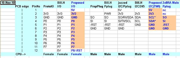
In other threads Bill, jazzed and I discussed a standard pinout for I/O, I2C (TWI) and extended PropPlug. I had intended to use the PMod 2x6 as per Digilentinc. However, discussion made me re-think.

Here is a proposal for the 8 pin I/O expansion header based on the Parallax ProtoBoard. 10 pins are already defined but Bill and I (maybe others) require +5V and I require an extra I/O pin sometimes and -Reset other times. Bill has used 11 pins and I propose to make it 12 pins. Obviously a 10 pin pcb will plug into the 12 pin (I have added a pin each end because this makes sense on the protoboard).
Bill has used the pin after P7 as +5V but I would prefer that +5V be the other end (before the +3V3) with the +3V3 and GND. Then I would use the pin after P7 as an optional extra I/O or Reset pin, or no-connect, as required.
Bill: Is it too late for you to change and what would be the impact???
Also, here is a proposal for the PropPlug and I2C (TWI) extension. You will note I intend to use a 2x6 way right-angle pin header with the PropPlug on the top pins and the unused 2 pins will be cut off. The I2C/TWI interface will be on the lower row of pins. This is to conserve pcb space.
Bill & Steve: I would prefer if SCL and SDA were swapped to make the SCL (an output) equivalent to the SO pin on the PropPlug. Is this too late for you to change???
NOTE1: It is just a cleaner solution IMHO. I am not committed yet so please say so if you cannot accommodate the change.
NOTE2: I have depicted the pcb edge so we all get it the same way around.
NOTE3: My pcbs are not designed to stack, but rather plug into one another on the same horizontal plane. So, I am actually using right-angle sockets for the Port I/O expansions and right-angle pins on the connector boards. However, vertical sockets and plugs(pins) can be provided as an alternative. I also have purchased housings plus male and female terminal pins so that cables can be made easily.
622 x 201 - 30K
Comments
Sorry, it is far too late for me to change my 10/11 pin connector because:
1) Your pinout would not fit the connector spacing on my existing large boards:
Morpheus, Mem+, Proteus, Propteus,
Morpheus+, Mem*, pPLC, CPUModule, svt1
2) The cange in 5V position would require me to re-do above boards and I/O modules below
DIG-IN-8-V, DIG-OUT-8-V, ANA-IN-8-V, ANA-OUT-4-V
ANA-OUT-8-V, MCP3208-IN-V, RTC-FRAM, uSD-Ethernet
3) It would require changing about five boards currently in the works
Regarding the I2C connector:
Sorry, again, I can't change it - it is on too many of my existing designs. I chose 4x1 for simplicity's sakes.
I have my I2C connector on the current existing boards:
Morpheus, Mem+, PropCade, Morpheus+, Mem*, svt1, pPLC, FRAM-I2C
It is coming on another half a dozen boards that are "in process".
I realize that many of the boards I mention above are not available for sale, but they have all been prototyped and are currently being tested - so it is too late in the design cycle for a new connector, as it would cost me too much to re-proto and re-test all the designs - never mind replacing already produced boards that use the connector - with over 100 in the field.
And a large number of boards ARE being shipped, and I have stock of production boards for them:
Morpheus, Mem+, PropCade, svt1
And I will be ordering production runs of all the other boards within weeks.
Having said the above... if you swap SCL and SDA on your proposed connector, my 4 wire one would fit it.
Sorry, I really cannot accomodate.
*NOTE* svt1 is a semi-custom board for a customer, that is in use in the field, and will be in production for years.
If you put your P8/RESET above 3V3, and leave 5V where it is on my connectors, you will be compatible with the LARGE number of boards above
10/11/12 I/O Pinout
It's no problem to swap 5V and Reset (or an extra I/O) to opposite ends. It was more a cosmetic thing if it was not too late.
I2C Pinout
I will swap SCL & SDA too.
Hindsight is a wonderful thing. If we had realised earlier we could have used the I2C as 5V, 3V3, Gnd, SCL, SDA, nc and it would have been compatible with my proposed I/O pinout too (using P0 & P1). Never mind.
Jazzed (Steve): Is this OK with you??
PS: I expect to be off-air for 2-3 days so don't worry if I don't reply.
I wish I'd thought to put more space between the two 10 pin headers on the original Morpheus/Mem+/Proteus/Propteus boards - I based the original spacing on having direct short straight traces come out from the Prop pins.
For the I2C, I just tried to adhere to the KISS principle; in retrospect I wish I'd gone with 3V3, GND, SDA, SCL so that I2C modules would also plug into the EXP (10 pin) connectors on different pins - not just a 4 pin connector next to the Prop.
The good news is that I have a LOT of cool modules coming - for both EXP and I2C connectors
FYI, I label 10/11 pin ports as 'EXP' if they connect directly to Propeller pins, and 'ALT' if they connect to other parallel I/O. I make the distinction as some of my I/O modules require Prop pins, but a lot will work fine from any form of 8 bit I/O.
I really like the 2x8 I2C/PropPlug pins mostly. There appears to be an "extra" ground pin that could be allowed to enable a 3-wire SPI interface for example. I'm also curious about the non-connects on the PropPlug side.
I'm not at all fond of having 5V next to pin P7 because it limits "extention" possibilities. Sorry Bill, it's not personal.
Now you guys might think I'm nuts, but on a recent board design I've combined the 8 bit bus and I2C(TWI) pins to achieve Propeller pseudo-DMA (5MB/s inter-Propeller data transfers).
What that does is lets me use a parallel burst with I2C signalling. On the "expansion" end of the bus currently is a Propeller that has VGA, 2 PS2/USB connections and other miscellaneous pins.
With a "hybrid I2C" bus in mind, the pin-out could be like this on single row 2.54mm spaced header: 5V, 3.3V, GND, System Reset, D0-7, SDA, SCL, + 6 reserved pins.
In "pseudo-DMA" mode, SDA is used as a "terminal count" once the transfers are set up and SCL is clock.
I'm not suggesting that is a perfect pin-out for a connector for the Propeller Proto-board (though it could be used), but it works nicely on the Propeller-Platform footprint. I can also see using the connections in a slot oriented bus configuration.
+5 ended up after the pins as that is where it made sense on new revisions of Morpheus/svt1/etc layout wise. In retrospect, it would have been better above 3v3, however it is now cast in stone due to the number of boards using it.
Frankly, most of my boards only use the 10 pin (3v3, GND, P0-P7) Protoboard format, which is what I had in mind when originally designing my stacking approach, but Sapieha (correctly) pointed out that it is very handy to have +5 available for some boards.
No worries - for "extension" purposes, I use two of the 10 pin (or 11 pin) connectors, with one empty unused position in between. See my Proteus/Propteus/Morpheus/Mem+ boards for an example.
Nice work on the 'pseudo-dma' transfer.
If You look on Propeller ProtoBoard ---> If You expand connector on both sides YOU can't place 4 Break-Boards around Propeller.
My office is overflowing ProtoBoard things
The 2 unused pins on the PropPlug pinout are going to be 5V & GND and if not required, the pins can be cut off leaving the standard 4 pins. This is so I can input 5V if it is not done via the mini-USB-AB, which is the preferred method. The SI/SO pins also connect via resistors and links to the mini-USB-AB connector. I intend to use scanlime's USB code hopefully to remove the requirement for the FTDI chip.
I agree, the expansion of the P0-7 is much better to continue. Maybe where required I will expand there. I have thought about a link to chamge 3v3 to 5v. All this can be fixed with the cables I have coming.
Got to go but I have a few more ideas I would like to share.
If you do add +3.3 and +5 instead, leaving the one ground, it can be made compatible
Here's some compromise ideas.
I have ordered 12 pin connectors and my pin 2 will be the beginning of 3v3, gnd, P0-P7. Pin 1 will be 5V on my cpu pcbs. Pin 12 will most likely be linkable to 5V or -Reset or an extra I/O which are required for a few specific (specialised) modules coming.
Space is an issue for getting 2x6 pins for the propplug & I2C header. I had intended to use the spare 2 pins of the propplug section to be an alternate 5V & GND input to my pcb. I thought if the power was not being fed here, then those pins could be cut off.
I am still contemplating, so my VGA pcb has 12 pins and if 5V is required for the monitor (I have never tried without 5V so not sure how many monitors actually require it) it can be linked from my pin 1 or pin 12.
I have not really thought much over the past few days.
I never connected 5V to a monitor, tried 5 different monitors (1CRT, 4 LCDs). Apart from sync problems... all worked well.
Ale
"2x Header connector" - fully compatible with my modules
"Proto Conn" - compatible with my modules that don't need 5V
"18 SIP Conn" - first 10 pins compatible with my modules that don't need 5V
"12 pin DMA" - first 10 pins compatible with my modules that don't need 5V
"I2C/3Wire" - totally incompatible with my upcoming I2C modules and existing processor boards
"PropPlug" - when V+ is 3.3V compatible with my comm modules
My I2C connector is:
3v3
SDA
SCL
GND
If you used
3v3
SDA/DIO
SCL/CK
GND
GND/CS
then it would be compatible with my I2C, just adding a pin to allow for 3-wire.
That is pretty compatible; all my 10-pin 3v3 only modules would work with that configuration, and when pin 12 was linked to +5, even my 5V modules would work
The following 2x5 might work for you - and its compatible with PropPlug, my comm plugs, and my I2C header; also with cluso's i2c/3wire if he makes the changes I suggest
I usually wire the +5, but I've also run without it. I think vast majority of monitors don't need the +5.
I just realized the TinyTwoWire module has Bill's I2C pin config. So the drawing I posted before is wrong.
I'm still struggling with the need for separate 5V on the I2C/SPI and PropPlug pinout. I reordered pins on the I2C/SPI and added an optional extra pin for 4 wire SPI input.
Above is the pinouts (just the I/O for now). You will see I am using my pin 1 (first pin) for +5V but can also link +5V or P8 or -Reset or anything else on my pin 12. So, it is compatible with Bill's 11pin series. It is also compatible with Steve's proposed headers.
BTW the 18 SIP is actually 19 pins on previous drawings???
So, may I suggest that whereever possible, the +5V now also be included at the top of 12 pin connectors?
I have 1x12 pin connectors ordered in ST (straight), RA (right angle) in both male pins and female sockets. I also have ordered 1x12pin cable housings and the crimp male and female pins for #22-28AWG wire. I have plenty if you are interested. I have pricing, but not ordered, 1x12 pin straight female sockets with 10.5mm pins (for stacking).
I am still thinking about the PropPlug, I2C, SPI, etc connectors. I must say it's a shame they don't follow the I/O connector (5V,3V3,GND,SI,SO,-RST...) as we could just swap them anytime. PCB space (board edge) is a problem for me.
The 2x12 connector could have GND or KEY instead of AUX. There is of course a logical 2x20 extension to the 20SIP which would have GND or KEY next to RST*.
I would push for Propeller Platform connector pin-out, but mechanically it's just too different.
I like Yours solution
I looked at using the micro-USB-B but I have a Nokia phone with it. It is difficult to see which way around it goes and I was in the shop when a customer had pushed the cable in the wrong way. The salesman said "another phone for the trash - happens all the time". And the reality is it only saves a small amount in space.
So, I decided on using the mini-USB-AB. Many phones and cameras use the mini-USB-B. The mini-USB-A cable is a speciality for host devices so I wanted that option too on the same connector. Best of both worlds.
What this means is I have 1.5" pcb edge to fit a mini-USB-AB, a microSD socket (which is larger than the one I used previously because of cost), and a 2x? RA pin header. The uSD takes 0.65" and mini-USB takes 0.45" leaving 0.4" for a 2x4 header.
Yes, we are compatible then
On future boards, where I have space for it, I have no problems adding +5 on top.
Sounds good... FYI, for stacking, I use .506" legs - due to height of PS/2 connectors.
<humour:on>It would be difficult for PropPlug and I2C to follow you new pinout as they significantly pre-date you proposed your pinout on production boards
If you re-arrange your proposed pin order, you can still be compatible with H-COMM (my propplug+3v3) and I2C... and I alrady have RS232 and RS485 plugs, with more plugs coming! There is also an FRAM/RTC board Sapieha designed for the I2C pinout, and I have several more coming.
Looking at your latest diagram's larger connectors:
- your "2x Header" connector would be able to take one of my 3v3 only modules
- your "Proto Conn" connector would be able to take one of my 3v3 only modules
- your "20 SIP" connector would be able to take one of my 3v3 only modules
- your "14 DMA" connector would be able to take one of my 3v3 only modules
That is, none of your larger expansion connectors would be able to take any of my 5V modules.
- your I2C/SPI is a superset of my I2C, so you could use my I2C modules
- your PropPlug is a superset of mine, and could use my comm modules
Cluso's 12 pin would be compatible with my 5V modules when 5V is present after P7, and with my 3v3 modules in all cases.
FYI, the 5V modules in my production pipeline are:
8 input analog module, 0-5V
8 output analog module, 0-5V
for industrial uses. The built proto's are sitting beside me, waiting for their turn for drivers
Due to mechanical issues (fitting two modules side by side) on my processor boards, many of which I have already producted, I do not have room to add a +5V on top.
I had an SPI-only version of this in mind, but Sapieha convinced me to add I2C to it. We kicked this around for a week or so before UPEW. Of course none of you has to use this, but I will have many interesting modules for it - and several "motherboards" that accept modules with this pinout, and you are all welcome to use this connector format.
5V chips are required to put a 2k2 resistor between their output and MISO (and SDA) for level translation
Note that the processor boards will still have the simple 4 pin I2C only interface, and not every board for this 2x5 connector will even implement any I2C chips.
I assumed it is polarized, or at least in my head, it should be.
Didn't you get my reply?
Yes, I intend to move to a connector like that, but not 90' one like in your pic, but for now I have just been using 4x1 male .1" headers.
I realise the downside of not having polarised connectors, but any connectors apart from standard pin stake ones are difficult for hobbyists to buy. This is our market here. Commercial products are different.
So I have standardised on using the standard pin stakes size. I have housings of various sizes coming (again not polarised) and the pins (both male!!! & female) so that conversion cables can be made simply.
1) For I2C, a stacking bus based on pins 4-8 of DIP8
3v (pin 8)
Vss (pin 7)
SCL (pin 6)
SDA (pin 5)
Vss (pin 4, optional)
You can see what I'm aiming for in the attached photo of a Si570 clock module. It reminds me somewhat of "number 5 is alive" from those 80's "short circuit" films.
2) 20/40 pin 0.1" - similar to 20 SIP outlined above, but with I2C first ie
SCL
SDA
Vin - can be any voltage including single solar cell ~0.6v to industrial 24v DC
5v - can alternatively be LiPo ie 3.7~4.2v DC
3v
Vss
P0
...
P13
The whole "5v vs P8" thing keeps coming up with respect to the proto board. For instance the other design shown below works better with the 5V after P7, rather than next to 3v.
Here is my module that use 4pins I2C Bill described.
I use it as both EEProm and RTC to test PropCade
Can even be used IN Dip8 EEProm place and on ProtoBoard with 10 pin header that are compatible with it
In my case, for the stackable DIP8, I want it to work with any DIP8 socket and that dictates I use pins 4-8 as shown, and then pins 1-3 are free for user functions (or external "field" connections).
The SPIX interface is interesting too. There is a similar bus pirate 10 pin connector, but it "overloads" the SPI, I2C, JTAG and Serial on the same pins. Info is here
http://dangerousprototypes.com/docs/Bus_Pirate_I/O_Pin_Descriptions
My module can be used in that mode