

Please help check my Robot Design
 william chan
Posts: 1,326
william chan
Posts: 1,326
Hi,
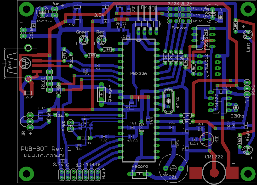
This is my latest Propeller robot design.
The files are created using Eagle version 5.
Please help check to see if anything is wrong or can be improved.
Thanks.
Last Edited: 12 Nov 2010 11:56am - Solar Charging Port added
12 Nov 2010 6:00pm - One more bypass cap added near RTC chip. Spare IO headers removed.
Added "record" button to start recording your voice into the MicroSD card.
12 Nov 2010 9:00pm - Corrected the outline for the tact switches
18 Nov 2010 9:30pm - Added DS1621 Temperature Sensor IC
sch
323K
1073 x 773 - 73K
Comments
Can you add some bypass capacitors? 0.1uF, basically one per chip, and the propeller needs two. For the propeller they natrually fit across the power supply pins as close as possible to the chip.
Thanks.
There is one 10uF 1206 ceramic capacitor under the Propeller chip.
I figured one 10uF is sufficient.
I just mindlessly put them in.
I did read a very learned article once in Electronics and Wireless World about the dry topic of bypass caps. It had lots of maths looking at the inductance and capacitance of typical PCB traces, as well as the timing transients. The final conclusion was something similar to the above, so I know there is logic in this.
I have an endless supply of the required capacitors thanks to all the junked boards I desoldered when I was younger. A misspent youth spent dumpster diving at my local university. Mind you, I think they were once computers worth millions of dollars!
Mac,
The 0.33uF also under the Propeller is an ac coupling to the audio amplifier LM4990 which is the extremely small ic. It is not a bypass cap.
Dr Acula,
Nowadays power regulators are faster and their datasheets specify only 1uF at the output, but i put in 10uF ceramics at the outputs anyway.
Also remember that this robot is battery powered.
LOOK even always with what LOAD!
Bigger LOAD bigger capacitance on that CAPACITOR.
NOT to mention some decoupling's Cap's on BATTERY rails before Regulator.
The data sheet says:
"The circuit designer should verify the stability by applying line step and load step testing to their system when using capacitance values greater than 22 μF."
With an low ESR, you will have a high rush-in current when applying power.
To the board:
Sorry, but the layout looks quite .. er ... sub-optimal.
Why do you mix SMT and THT? Why don't you dedicate the soldering side to GND, try to route everything on top and just make some short traces at the bottom? I guess you could reduce the board to half of the size.
Nick
Thank you for your comments.
The board size is fixed and cannot be made smaller because it supposed to be fitted to these robot parts
http://www.parallax.com/StoreSearchResults/tabid/768/List/0/SortField/4/ProductID/304/Default.aspx?txtSearch=boe+parts
The way the board is designed seems odd but it actually allows the use of non-plated-thru-hole double sided PCBs to save costs.
Of course you can also use PTH PCBs if you like, but if you use NPTH PCBs, you need to solder the front side as well, that's why the top (red) tracks are reduced to a minimum.
Using some thru hole parts allows resistors to act as "jumpers" to jump over tracks, allowing more tracks to be placed at the bottom.
Smd parts are used where space is tight.
Ah, that makes sense. Well, not to me, because I don't etch my own boards. But I guess you do.
You can still route one trace "through" a 0603 resistor.
Still, I think you can gain something by having a big ground-plane.
The +5V (IIRC) on the left side around the USB-connector makes a funny route.
In Eagle, click on "show object" (= the eye-icon) and click onto a trace. Makes finding shorter routes much easier.
Nick
Actually I don't etch my own boards either.
The PCB factory just offers NPTH boards at a lower cost.
I can't use tracks smaller than 16 mils because they also offer silkscreen-etching-process to make the tracks which is cheaper than the photo-etching-process.
I will try to improve the routing around the USB connector.
Thanks William. I was just curious about Dr Acula's remark about why he needs to add a 33uF near the prop on his design.
Hi Sapieha,
Your remarks about more capacitance at both the input and output got me thinking about whether my capacitance values are large enough.
I checked back the regulator datasheet, and they confirm that 1uF at the input and 1uF at the output is sufficient capacitance for the full load of up to 250mA.
The regulators I am using are MCP1703-5v and MCP1703-3.3v.
Both claims a quiescent current of only 2uA when idle!
That's why my robot has no power switch....
Attached is the regulator datasheet.
Yes, I probably over engineer the capacitance.
1) I am using switching regulators. The standard circuit is here http://www.national.com/mpf/LM/LM2575.html#Overview I am using 470uF rather than 330uF as I got a job lot. This capacitor is part of the switching circuit so it needs to be physically close to the switcher and have thick power traces.
2) I put 0.1uF ceramic/film capacitors next to each chip. This is fairly standard practice. Many circuits will work fine without them, especially slow circuits (eg a 555 flashing at 1Hz). But at fast speeds you will get glitches and mysterious behaviours. You can see this on a CRO. When I grew up with electronics I could not afford a CRO, but many of my circuits were audio circuits, and you could hear the pops and clicks of the digital part of a circuit if you left out the bypass capacitors.
3) I like to have a large store of energy nearby things that are going to need them. Possibly a propeller chip is not going to be something that does this (though it might be if every pin was connected to a led and you turned them all on at one time). But one device that very much needs its own local store of energy is an SD card. You can go into the details of ESR and inductance and capacitance. I like to think of things in a simpler way. Say your chip suddenly turns on a led. The energy comes from a 0.1uF cap and this prevents the supply rail from drooping. The 0.1uF cap responds very quickly, but the downside is that it runs out of charge very quickly too. A bigger capacitor responds more slowly but stores more energy. For an SD card drawing a few hundred milliamps, what this means is that the current in the main power supply traces rises more slowly, and that translates to more gentle transients, and in a practical sense on the propeller, that means less glitches on the display.
Wikipedia says http://en.wikipedia.org/wiki/Tantalum_capacitor "They are also often used for power supply rail decoupling in parallel with film or ceramic capacitors with low ESR and reactance at high frequency."
For this particular design, the tantalum caps are probably overkill. Then again, a robotics environment can be even harsher in terms of sudden current draws. I'm thinking of many discussions on another microcontroller forum along the lines of "why does my microcontroller reset when I move a servo".
As I'm not English speaking You and others can maybe have little problem to understand me BUT.
That conditions that them show on data sheet to this REGULATOR are for ideal conditions.
Now if YOU look on data sheet to PROPELLER -- Propeller are not CONSTANT current device. As You maybe already saw its current can vary in time very fast (COG's start/stop, How many COG's in time are used and much more). That can dry out CURRENT from Regulator very fast (That automatically draw VOLTAGE down) it was one of problems with earlier Paralax ProtoBoards before them added some extra TANTALUM capacitors to them that problem had impact on PLL's in Propeller.
Dr_Acula: Yes, I probably over engineer the capacitance.
NOW: That Capacitor near Propeller HOLD extra power to give it back to Propeller in times it needs without draw down VOLTAGE on its Power pins (That give stability for PLL on Propeller) AND prevent to draw out down Voltages on other IC's on PCB.
THAT give Yours PCB good stability (YOU WIN).
Your English is very good. Much better than my Swedish! I love going to Ikea and reading the books on the shelves - they are all in Swedish.
I did not know about the PLL problem with the propeller. It is another good reason to add a tantalum. I found out about the SD card needing a tantalum the hard way - I left it off a board design and it did not work.
Capacitors are cheap if you buy them in bulk. I buy many 470uF electrolytics, 33uF tantalums and 0.1uF monolythic ceramic bypass capacitors. Eg in quantities of 100 the 470uF electrolytics are 10c each. The 0.1uF caps are 3c each. Tantalums are worth searching for a good price - I got a whole lot on ebay for a good price. Futurlec are a bit expensive for the 33uF ones ($2.40) but the 22uF 6.3V ones are only 24c. So if I was buying some more from futurlec I would get those.
Ebay is worth a look though. I'm just a hobbyist but it is amazing how fast a hundred 0.1uF caps can disappear, and these parts are a lot cheaper in bulk.
Also, there is always recycling. I cannot bear to throw away a board with big electrolytics or tantalum capacitors (though I can't be bothered desoldering 0.1uF caps).
Thanks.
One addition to my explanations WHY that happens? -->
Most of REGULATORS need some u-Second to stabilize Voltage BUT Propeller in some cases can change CURRENT needs in some n-Seconds and time between REGULATOR can stabilize to new conditions IS time that CAPACITOR give it.
Ps. "I did not know about the PLL problem with the propeller." ---> It is NOT problem in PLL in Propeller --- THAT problems have ALL PLL's if You not give them stable VOLTAGE. BUT in systems that have constant CURRENT consumption REGULATORS can hold stable Voltage and them work correctly. PROPELLER as I said are more difficult AS IT IS VARIABLE CURRENT device that can change current needs as fast as some n-Seconds.
A 10µF capacitor stores enough energy to supply 100 mA over 30 µs with a voltage drop of 0.3 V. (hope my numbers are right).
A LM2937's output voltage changes by just 50 mV when the load change is from 0 to 500 mA with an 10 µF on the output.
Depending on the circuit, a big capacitor on the output can result in a too big revers-current through the regulator when removing power. -> kaputt
I don't know why that big-capacitor-fery-tale is told over and over again.
Nick
You are mostly Correct.
It is WHY I said in my first post on IT!.
LOOK on this link
http://forums.parallax.com/showpost.php?p=952742&postcount=8
THAT is only correct IF PCB's current consumption is very litle and CAPACITOR is MUCH to BIG. BUT I never had that failure as all REGULATORS have over current protection --- On other hand had many undesirable problems without correct Capacitor values in relation to TOTAL current consumption on entire PCB!
Ps. Many times needed to reconstruct some industrial PCB's (that was in some equipment that others constructed) that have be used and had undesirable problems TO have them work correctly
I said reverse current not over current!
Or do I have to use more than one color to make that clear?
Nick
YES and NO.
It is why on building correct dimensioned REGULATOR circuity IN Voltage Capacitors need be dimensioned to have more time to drive it that time to dry Voltage from Regulator (That prevent regulator to work in opposite direction).
You not need use different color's I understand what You are said.
BUT i think I'm are not correctly clear im my explanation and it is that why give some misunderstanding's.
Thanks Dr_Acula. I never thought of SD requiring a cap! I focus more on servo rather than other peripherals. That might explain why sometimes the SD card might have seems to fail reading a block when the servos are moving rapidly (I think that might be the bug on the failures I'm seeing) .... I'd better go add a cap & test. Guess it was the right choice selecting Propeller as the main uP for my current project rather than Atmel or others. People here have the true spirit of helping others
Sapieha,
So, you mean it is a good practise to add more cap especially for Propeller in robotics environments? I'll keep that in mind especially after what Dr_Acula mentioned about.
Thanks.
That is true, and the simple answer is to have bigger capacitors on the input than on the output. I have pulled to bits a number of 'wall warts' and a common value inside those is 4700uF. I think if you are putting, say, 470uF on the output, put at least 470uF on the input. Maybe more (I sometimes use 2200uF). And the input capacitors tend to be bigger as they need a higher voltage rating, eg 16V or even 25V on the input, but 6V caps on the output.
You can salvage a lot of these bigger caps off old PC motherboards.
@William, do you have an updated version of the board?
I have posted the updated design in the first post.
There are only small routing improvements and also I have changed the 470uF at the battery post to a 10uF Tantalum as I am concerned about the leakage of electrolytics.
This robot is supposed to be able to "standby" for at least 3 months on 4 AA batteries so all leakages are a concern to me.
Sapieha says should add larger capacitors.
Nick says should stick to smaller capacitors.
I re-read the MCP1703 datasheet and the word "ideal conditions" can't be found anywhere, so I am sticking with smaller capacitors.
Please note that the servos use the unregulated battery power directly. It does not take power from the regulators.
There is a P Channel mosfet that acts as a high side switch to power off all servos when not in use.
If you are concerned about leakage, there is another problem you might face - the internal leakage of capacitors. It is possible that the capacitor is going to draw more current than anything else, including the micro and the self leakage of batteries.
You might like to look at low leakage electrolytic capacitors.
Where did you find it? Directly behind the bridge-rectifier? If so, it has to reduce ripple, that's it.
But admittedly, the voltage regulator that William selected is extremely slow. Look at the data and compare it to the one I named. You'll be shocked how much the output voltage changes with a sudden current change.
Nick
The newer (lighter) switching reg wall warts are more complicated, and are likely to have much better regulation too.
@william, what sort of batteries are you using - dry cells/alkaline/rechargeable. If rechargeable, there is also a not insignificant self discharge rate. If alkaline, it might end up chewing through the batteries! Is the robot designed to hide in corner and only come out and annoy you occasionally? I've pondered designs where the robot is smart enough to find its way behind the curtain and seek out sunlight, and keep its batteries topped up with a small solar cell. I wonder if such smarts could be programmed into a propeller?
Your idea about Solar Charging is ingenious!
I have added a solar/charging port at the rear end of the robot now. ( see first post )
It may be possible to use this panel
http://www.parallax.com/StoreSearchResults/tabid/768/txtSearch/solar/List/0/SortField/4/ProductID/619/Default.aspx
I wonder if this solar panel has a built-in diode....
I placed it at the rear end in case the robot would be smart enough to guide itself into its charging station in the future.
I designed this robot to cater to both Alkaline and NiMh rechargeable batteries.
Most people would design a propeller board by providing the regulated 5v as input to the 3.3v regulator. This would be a problem when the battery voltage drops below 5.5v
To avoid this problem, I provide the battery voltage directly as input to the 3.3v regulator so that the Propeller and all other 3.3v devices can continue to operate to as low as 3.9v battery voltage. No need Boe Boost!
Servos also take direct battery power so it is less likely to cause brown-out resets.
The only problem is when a very new alkaline battery is installed, this may provide up to 6.5v to the servos which may cause the servos to ignore 3.3v signals from the propeller.
The solution was to provide a high side mosfet switch which will reduce the servo voltage by about 0.2 volts and also has the added bonus of being able to totally power off all the servos.
The Hack port is for the optional Gadget Gangster Micro-SD module.
http://gadgetgangster.com/find-a-project/56?projectnum=230
"ideal conditions" = Constant over time (80%) current drawn from Regulator
That condition You can't never have on Propeller.
On 2 of Diagrams them have in data sheet them show Dynamic LOAD response (Figure 2-28, 2-29). I think that Diagrams SAY all
Look on times that regulator needs to stabilize Output Voltage (It is little more that that TIME (and some more) Capacitor need have enough current to give Yours PCB ---> to have Voltages stable on it.