

Spencer-Brown Counter
 Heater.
Posts: 21,230
Heater.
Posts: 21,230
Whilst discussing the meaning of pi and hence the existence or not of mathematical objects/concepts I took another look at the work of George Spencer Brown, his famous work "The Laws of Form".
http://www.lawsofform.org/
http://en.wikipedia.org/wiki/Laws_of_form
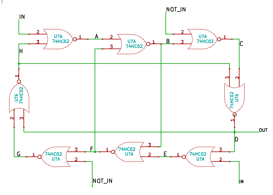
In doing so I stumbled across a binary counter, or at least divide by two, stage that he devised. It uses only NOR gates and is quite unlike any divider stage I have seen before.
http://www.lawsofform.org/counter/index.html
Here is my rendition of it in KiCad.
Anyone out there got a logic simulator to quickly verify this works as advertised?
Edit: Updated schematic with annotated signals.
http://www.lawsofform.org/
http://en.wikipedia.org/wiki/Laws_of_form
In doing so I stumbled across a binary counter, or at least divide by two, stage that he devised. It uses only NOR gates and is quite unlike any divider stage I have seen before.
http://www.lawsofform.org/counter/index.html
Here is my rendition of it in KiCad.
Anyone out there got a logic simulator to quickly verify this works as advertised?
Edit: Updated schematic with annotated signals.
929 x 663 - 12K
Comments
I have SwitcherCAD (LTSpice) running under Wine on Linux. It never occurred to me to use it for logic simulation:)
Anyway I updated the schematic in the first post with labelled signals. and the simulated the thing with a little C program. Results show that it does indeed divide by two.
The more I look at it the more I think it actually just a Master-Slave JK Flip-Flop drawn in an odd manner.
In a D-Flip-Flop, there are two outputs, 'Q' and 'Q-Not'
If you take the 'Q-Not' and feed it to the 'D' input and use the 'Clock' as your data/frequency input, then 'Q' or even 'Q-Not' will show up as having half of the input frequency.
Here is an animation. It's the same schematic, just drawn differently.
http://www.youtube.com/watch?v=9nCg1eSnVTE
No need to worry about disappointing me, after starring at it for a while I came to the same conclusion.
It's just that Spencer-Brown had an odd way of drawing it. Still, I don't think the logic symbols were so standardized when he did it back in the early 60's and perhaps the nomenclature of the various flip-flop types as we know today was not in place either.
Well, OK I said JK flip-flop, almost same:)