

BS2 and electromagnet
 alnajjar1
Posts: 110
alnajjar1
Posts: 110
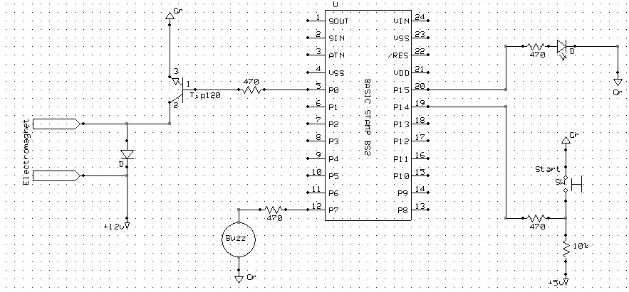
I am powering an electromagnet with a BS2 via a TIP120. The EM draws about 0.7A. The power supply is regulated and provides 5Amp.
The Stamp turn the EM on and of at intervals of about 10 seconds. There are other components (see attached circuit). The code is very simple turning the EM on and off when the switch is depressed. The circuit functions flawlessly for several days but then the Stamp dies completely, twice already.
All output pins including buzzer and LED are current limited 0.01 mA by the 470 ohm resistors so I don't think that is a factor especially when all of them are turned on together.
The EM and the Stamp are in the same enclosure. Do you think EM radiation and frequent rise and collapse of the field impact the Stamp's internal electronics?
any thoughts?
Al
883 x 411 - 119K
Comments
Also, to 'harden' the I/O pin driving the TIP120, you could also put a reverse biased diode there, but I tend to lean more towards the diode across your coil not being adequate as the source of your failure based on your description.
The magnetic field should have no appreciable effect on the Stamp.
Is the diode used with the coil up to the task, in terms of current rating and voltage rating?
Still a bit surprised the damage was so complete.
I will use a solid state relay to turn the EM on and off that way there is complete isolation.
Al
I like SSRs,They work good in low freq App.s
'
I didn't see the power supply for the Stamp or for the Electro.Magnet. I would look at this before I tried something else with another stamp.
'
I'm no engineer, But I think the 470 ohm resister on the base pin of the TIP120 should have protected the stamp from BEMF. Could you post the power supply set-up?
I suspect this is were the problem is.
'
I would use a driver for the buzzer as well (BEMF).You could replace the buzzer with an LED and resister to get the code working for now.Then go back and make the buzzer work.
Moskog:
'
I've been using the BS2's for years now.I have some Stamps that run 24-7 and work flawlessly.
'
The only times I have had a Stamp ACT strange is when I did some strange wiring or I wrote some strange code!
Yes, same thing here. Never faced any kind of problems with Stamps in compleated projects, I also have several of them running 24/7.
The only ones destroyed were incorrect connections and Lighting Strikes.
Are you using the intrenal regulator..or an external +5 volt supply?
If using the internal regulator, what is the supply votage?
You may be overheating the regulator if you are using the same +12 volt power supply as the EM.
The buzzer and led both add to the load on the regulator.
It has to dissapate the extra 7 volts as heat and can damage the stamp.
I Always use an external 5 volt supply for the stamp.
You can regulate the +12 to +5 and filter it to keep the EM noise out.
I would also run the buzzer from a transistor connected to the output pin to take the load off the stamp.