Line Following Racing Robot
 John Abshier
Posts: 1,116
This robot handily won first place in the Dallas Personal Robotics Group Roborama 2010A last May. I did my first run with the base speed set to 75 percent. Since that run was successful, I did my second run at 100 percent speed. The course was mostly curves, six inch radius. My speed didn't increase much because most of the time the robot was turning. A test run a home resulted in a 14 percent speed increase (measured) even though the commanded speed increased 33 percent.
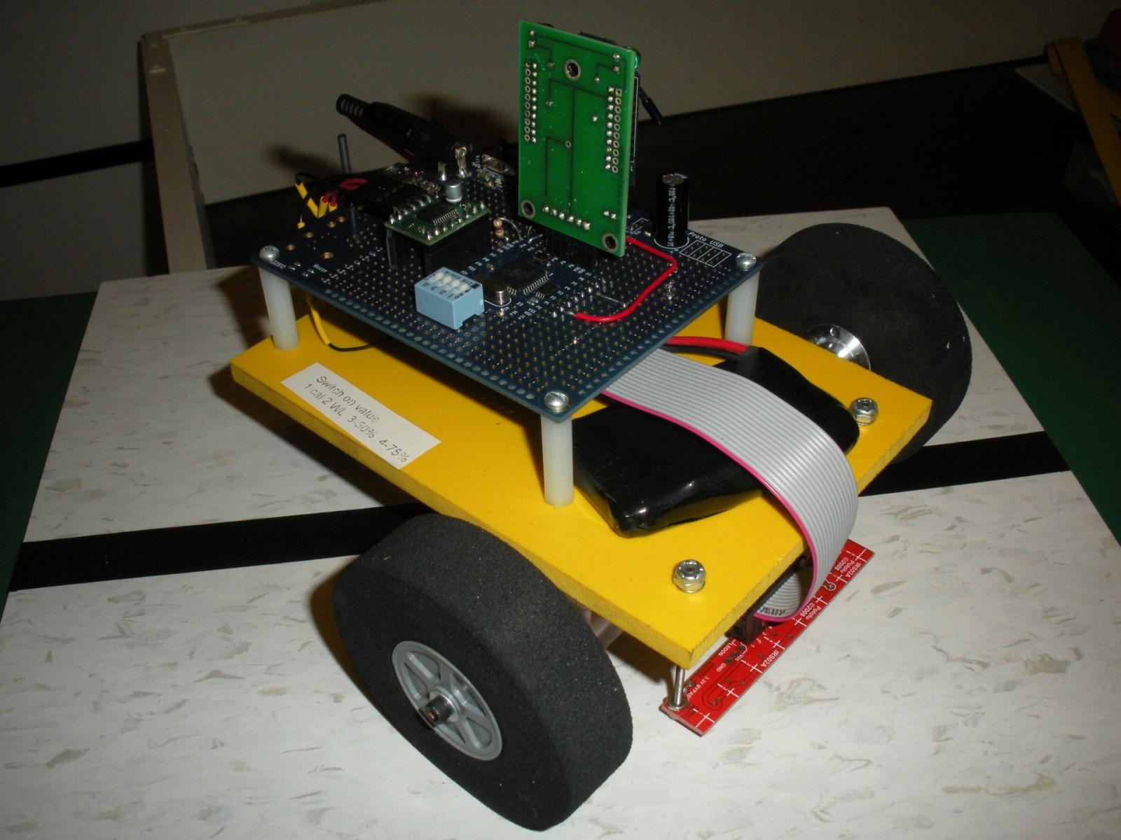
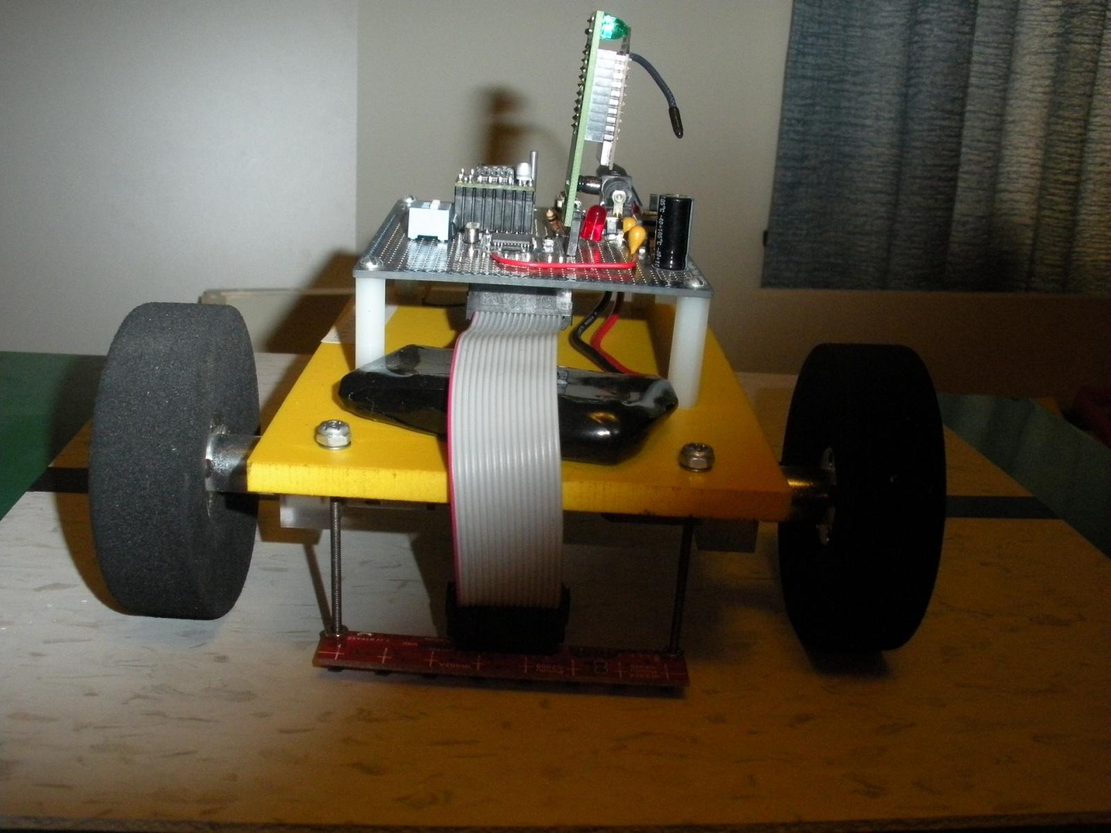
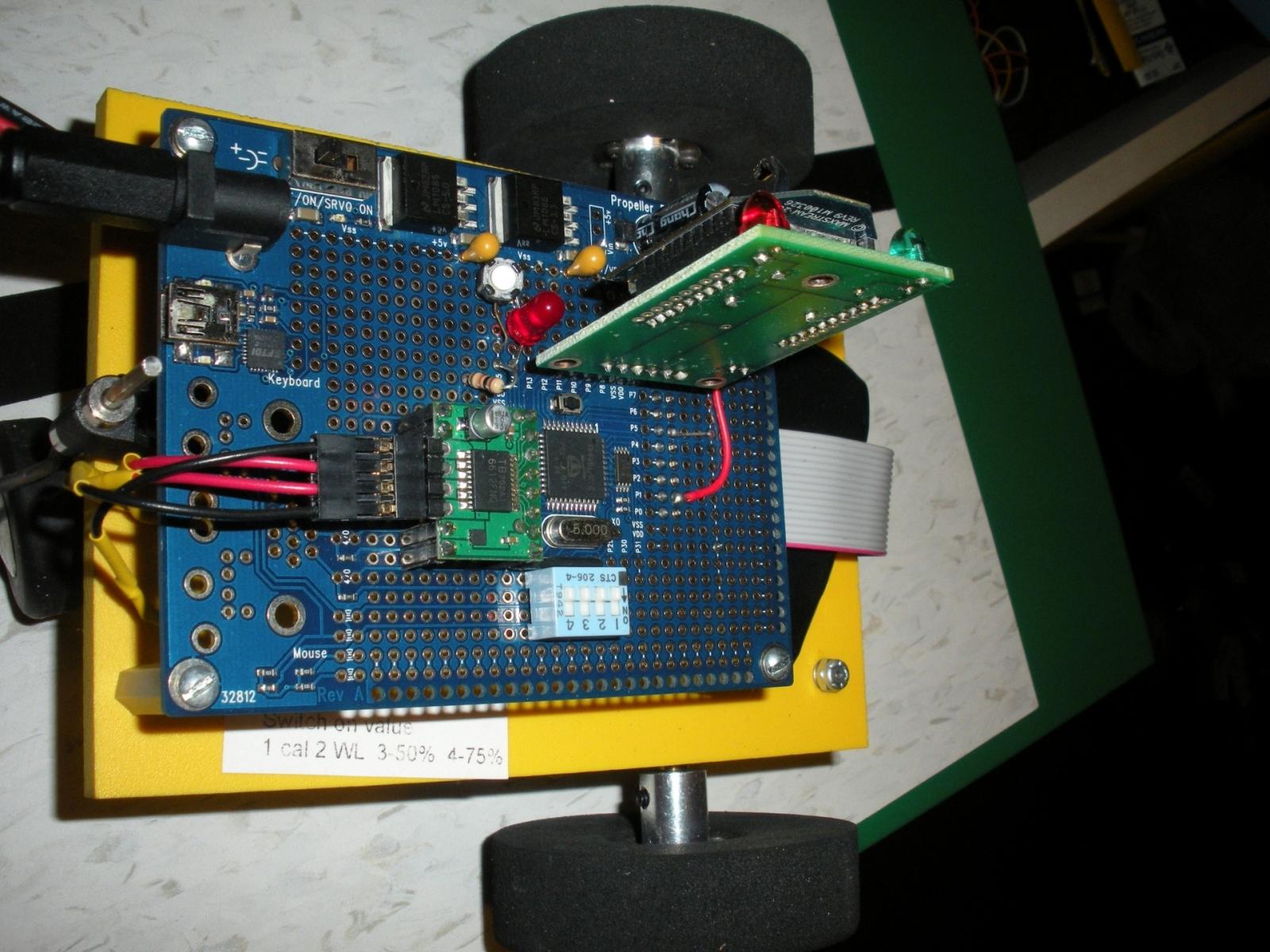
My initial design criteria was for light weight and low moment of inertia. The body is six millimeter thick expanded PVC. The controller is a stock Parallax Propeller Proto Board USB. The line sensor is the Pololu QTR-8RC reflectance sensor array. It is similar to Parallax's QTI sensor. The motor driver is also from Pololu, TB6612FNG. The battery is a 7.4 volt lithium. I don't remember where I got it or its capacity. Main wheels, 3mm hubs, and the tail wheel assembly came from Lynxmotion. Motors and mounts were some that I had from a previous robot. The dip switch has the following functions: Switch 1--select race or calibrate sensors. Switch 2--white or dark line. Switches 3 and 4 select various base speeds. The push button switch is a go/start button and the LED is for general information. An absolutely critical part is the XBee module. It is mounted in a carrier board from Selmaware (unfortunately no longer available).
The software reads all eight sensors and returns a number between -3500 and 3500 depending where the robot is in relationship to the line. A proportional, derivative (PD) controller tries to drive this error to zero. The hardest task I had was to determine the PD coefficients. Initially the robot would follow the line for a few inches and then go to never land. The XBee was used to send back the error value, motor commands, sensor status and some other information. I am using the XBee in simple serial mode and using Parallax's PST on my laptop. Looking at the data and sometimes copying the data into Excel to graph allowed me to develop PD coefficients that would complete my test course. Then I ran into another problem. I would change the coefficients and then ask, "Is this run with new coefficients better than the previous run?" It was hard to tell from just visually observing the run. Fortunately, the light bulb lit up. I summed the absolute value of the error term and counted the number of times the control loop executed. The number of times the control loop executed is a measure of speed, fewer is better. The average of the absolute value of the error term is a measure of smoothness in the run, smaller is better. Now I could tell if the coefficient change made things better or worse. The motor driver code is a mixture of SPIN and PASM. The rest of the code is in SPIN.
Future plans are to replace the wheels with 1/2 inch greater diameter ones for greater speed. A harder, and therefore less likely, change would be to move the Propeller Proto Board forward an inch and cut an inch off the rear of the frame. This should allow it to turn somewhat faster.
John Abshier


Comments
-Phil
John Abshier
Definitely, yes, you need to use lighting that you have control over.
-Phil
_richard
John Abshier
John Abshier
PS. I keep trying to preach the gossple of Propeller.