Shop OBEX P1 Docs P2 Docs Learn Events
Propeller - Sinking Current from the Seven-Segments — Parallax Forums

Propeller - Sinking Current from the Seven-Segments

John A. ZoidbergJohn A. Zoidberg Posts: 514
edited 2010-10-28 21:25 in General Discussion
This topic is about the Propeller, and also the Seven Segments, so I will post it here. Otherwise, feel free to move it. :D

I just had constructed a little clock with the Propeller, and with a pack of the common-anode 7-segments.

However, the displays are a bit too dim - it seems that I'm not sinking enough current. The thing is, I could have connected a ULN2803 inside, but what I feared is I will sink too much current into the Propeller, which is not a good idea after all.

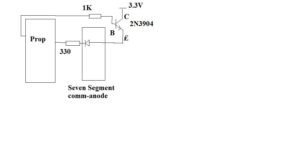
Here is my current schematic. If my calculation isn't wrong, the current is sinking 10mA, which is within the range of the allowed input current of the Prop.

So how do I properly sink the current without sinking those back into the Prop pins? :D
931 x 519 - 20K

Comments

  • max72max72 Posts: 1,155
    edited 2010-10-27 03:06
    Use a prop pin to drive the base using a resistor as you did.
    Connect emitter to ground.
    From Vcc go to Display and collector.
    The current is controlled by the resistor between the prop pin and the base.
    Current across this resitor (base current) is (3.3v - 0.7V)/R
    0.7 is the base/emitter voltage drop.
    At the collector you'll have the base_current X GAIN
    Gain is usually around 100-150, so the base current will be 0.1-0.2 mA.

    Massimo
  • max72max72 Posts: 1,155
    edited 2010-10-27 04:46
    This is the circuit I have in mind.
    A 20k resistor should drive the LED with 13-20mA, depending on the gain (supposing 100 and 150).
    528 x 566 - 4K
  • K2K2 Posts: 693
    edited 2010-10-27 09:03
    John, a quick check of your circuit shows that your LEDs are being driven at about 3.6 mA.

    A PNP transistor like the 2n2907 would allow you to pull the anode much closer to the positive rail. In that case I'd change the 330 Ohm resistor to about 160 Ohms.

    If you stay with your existing NPN design, I'd change the 330 Ohm resistor to about 120 Ohms
  • kwinnkwinn Posts: 8,697
    edited 2010-10-27 09:21
    What K2 said. There is a voltage drop across the 2n3904 transistor of around 0.7V and the forward voltage drop of the display led (typically about 1.8 - 2.2V) so the voltage across the resistor is only about 0.4 - 0.8V.
  • CampeckCampeck Posts: 111
    edited 2010-10-27 09:45
    can't you just do away with the transistor?
  • K2K2 Posts: 693
    edited 2010-10-27 09:50
    Campeck wrote: »
    can't you just do away with the transistor?

    Well, with all segments on, you'd have to supply the anode with 70 mA - a bit over Prop specs. You could always tie multiple pins to the anode, but you'd soon run into Prop dissipation limits that way.
  • ercoerco Posts: 20,260
    edited 2010-10-27 10:29
    BTW, "Sinking Current from the Seven-Segments" would be a great title for an action movie. Or maybe just "The Seventh Segment"...

    It's got Wesley Snipes and Bruce Willis written all over it.
  • John A. ZoidbergJohn A. Zoidberg Posts: 514
    edited 2010-10-27 17:00
    erco wrote: »
    BTW, "Sinking Current from the Seven-Segments" would be a great title for an action movie. Or maybe just "The Seventh Segment"...

    It's got Wesley Snipes and Bruce Willis written all over it.

    Haha, it's a funny coincidence! :lol:
    K2 wrote: »
    Well, with all segments on, you'd have to supply the anode with 70 mA - a bit over Prop specs. You could always tie multiple pins to the anode, but you'd soon run into Prop dissipation limits that way.

    How about interfacing the segments, from A-G to the sink driver, ULN2803? I just need to isolate the Propeller input pins.
  • K2K2 Posts: 693
    edited 2010-10-27 22:05
    How about interfacing the segments, from A-G to the sink driver, ULN2803? I just need to isolate the Propeller input pins.

    Why do you need to isolate the Propeller pins? A Propeller pin can sink 40 mA. You certainly don't need a ULN2803 to drive the individual cathodes.
  • John A. ZoidbergJohn A. Zoidberg Posts: 514
    edited 2010-10-28 04:53
    K2 wrote: »
    Why do you need to isolate the Propeller pins? A Propeller pin can sink 40 mA. You certainly don't need a ULN2803 to drive the individual cathodes.

    Oh, because the new seven-segs I bought requires a bit more current, it looks dim here on the board I'm working on.

    By the way, if I connect the LED + resistor and a 5V supply into the prop pin, I guess it is already beyond its specifications?
  • kwinnkwinn Posts: 8,697
    edited 2010-10-28 08:07
    Not necessarily. If the connection was (prop pin >> resistor >> led cathode >> +5V) the maximum voltage on the prop pin would be less than 3.3V. On the other hand you could not use a prop pin to drive the anode transistor directly regardless of whether it is a PNP or NPN transistor if it is connected to +5V.
  • kwinnkwinn Posts: 8,697
    edited 2010-10-28 08:17
    BTW, one reason for the dim leds is that you are multiplexing the displays, so they are only lit for 1/4 of the time. If you have 28 pins available you could drive all the segments on the 4 digits. Of course now you need 28 resistors as well, but no transistors. Another option is to use 14 pins to drive 2 digits at a time. Now you need 14 pins and resistors, and 2 transistors.
  • John A. ZoidbergJohn A. Zoidberg Posts: 514
    edited 2010-10-28 08:25
    kwinn wrote: »
    Not necessarily. If the connection was (prop pin >> resistor >> led cathode >> +5V) the maximum voltage on the prop pin would be less than 3.3V. On the other hand you could not use a prop pin to drive the anode transistor directly regardless of whether it is a PNP or NPN transistor if it is connected to +5V.

    I see.

    However, I have a 4-digit all-in-one 7-segment module by Avago, quite a medium sized one.

    The thing is it that the display is very dim despite being driven by ULN2803, and the digit selecting transistors.

    Or I would just go ahead, and do the one you suggest? I'll have to try on this one. :)
  • K2K2 Posts: 693
    edited 2010-10-28 08:43
    I see.

    However, I have a 4-digit all-in-one 7-segment module by Avago, quite a medium sized one.

    The thing is it that the display is very dim despite being driven by ULN2803, and the digit selecting transistors.

    Or I would just go ahead, and do the one you suggest? I'll have to try on this one. :)

    John, don't you see that the ULN2803 is part of your problem? It is a darlington array. A darlington transistor has two base-emitter drops. When you add two base-emitter drops to the voltage drop of the LED and the voltage drop of your anode transistor, you're out of voltage to work with.

    If you placed a milliamp meter in series with a digit, you'd see that you are achieving nowhere near 10 mA. And if you're not reaching 10 mA, what is the point of using a 500mA driver? The driver is part of your problem, not part of the solution.
  • John A. ZoidbergJohn A. Zoidberg Posts: 514
    edited 2010-10-28 08:49
    K2 wrote: »
    John, don't you see that the ULN2803 is part of your problem? It is a darlington array. A darlington transistor has two base-emitter drops. When you add two base-emitter drops to the voltage drop of the LED and the voltage drop of your anode transistor, you're out of voltage to work with.

    If you placed a milliamp meter in series with a digit, you'd see that you are achieving nowhere near 10 mA. And if you're not reaching 10 mA, what is the point of using a 500mA driver? The driver is part of your problem, not part of the solution.

    Ouch, no wonder the display looked starved. I forgot all about the minusing 2-BE drops there.

    So how to get around to making the display brighter? I searched around the net but they don't have much schematics for it.

    I'll have to drop the driver then.

    What is the best solution for driving even bigger displays? :lol:
  • CampeckCampeck Posts: 111
    edited 2010-10-28 09:03
    K2 wrote: »
    Well, with all segments on, you'd have to supply the anode with 70 mA - a bit over Prop specs. You could always tie multiple pins to the anode, but you'd soon run into Prop dissipation limits that way.

    Isn't the common anode tied to Vdd? That should be coming from the 3.3v reg and not the prop. and then you sink the cathodes with the prop pins. What am I missing?

    edit. ok...he is hooking up multiple of these up so he deactivates one of the segments by having the common anode on a prop pin. I get it now. lol
  • K2K2 Posts: 693
    edited 2010-10-28 09:10
    Campeck wrote: »
    Isn't the common anode tied to Vdd? That should be coming from the 3.3v reg and not the prop. What am I missing?

    The anodes are multiplexed. If you didn't multiplex the anodes, you'd need 28 Prop pins to drive all the cathodes. This way you only need 7 for the cathodes and as few as two for the anodes if you decode them. Four if you don't.
  • K2K2 Posts: 693
    edited 2010-10-28 09:24
    What is the best solution for driving even bigger displays? :lol:

    First of all, I don't know what Avago display you are using now, but none that show up in the catalog are very big by my standards. And if you're dealing with a 4-digit module, it's smaller still. So there should be no need for anything other than the Prop pins themselves to drive the cathodes. 40 mA is a lot of current for an LED, even in a pulsed situation.

    For the anode, simply use a PNP transistor like a 2N2907 or 2N3406 that you switch to saturation. That only has a voltage drop of about 0.2V. That will give you a pretty good voltage overhead to work with. At that point it's simply a matter of selecting the right current-limiting resistor. But that depends on your LEDs and the degree of multiplexing.

    If you're doing 1-in-4 multiplexing, you may as well use the whole 40 mA. LED's don't mind being pulsed.
  • John A. ZoidbergJohn A. Zoidberg Posts: 514
    edited 2010-10-28 09:45
    K2 wrote: »
    First of all, I don't know what Avago display you are using now, but none that show up in the catalog are very big by my standards. And if you're dealing with a 4-digit module, it's smaller still. So there should be no need for anything other than the Prop pins themselves to drive the cathodes. 40 mA is a lot of current for an LED, even in a pulsed situation.

    For the anode, simply use a PNP transistor like a 2N2907 or 2N3406 that you switch to saturation. That only has a voltage drop of about 0.2V. That will give you a pretty good voltage overhead to work with. At that point it's simply a matter of selecting the right current-limiting resistor. But that depends on your LEDs and the degree of multiplexing.

    If you're doing 1-in-4 multiplexing, you may as well use the whole 40 mA. LED's don't mind being pulsed.

    Here's the datasheet - http://www.avagotech.com/docs/AV02-0568EN

    It's a very casual 4-digit seven-segments with two decimal points for the clocks and whatever it is.

    I'll just get these transistors you mentioned and let the Prop pins sink the current instead then. :D
  • K2K2 Posts: 693
    edited 2010-10-28 10:35
    John, the datasheet is fairly interesting. This display tolerates a fair amount of current. I'm pretty confident that an average current of 10 mA will deliver all the intensity you can tolerate. But if it doesn't, there are ready solutions.

    BTW, with this specific display, a 3.3 V supply, and saturated PNP transistors driving the common anode lines, you'd need current-limiting resistors of about 33 Ohms to get 40 mA through an LED segment.

    (p.s: If you buy transistors by the bag like I do, they're only about $0.05 USD, each.)
  • kwinnkwinn Posts: 8,697
    edited 2010-10-28 21:25
    John, just keep in mind that if you are supplying 40mA directly from a prop pin to a segment on each digit for 1/4 of the time the prop pin is supplying 40mA 4/4 of the time. In other words 40mA continuously.
Sign In or Register to comment.