

Q6015L5 Wiring
 Macgruber
Posts: 20
Macgruber
Posts: 20
Hello!
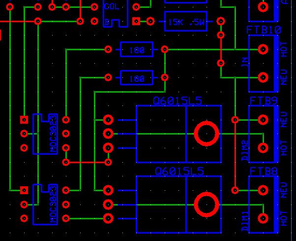
I need a little help... I am trying to create an AC light dimmer and have encountered some problems getting the triac to switch at all. The circuit is based on the nuts and volts article 146 (Dimming the Lights Fantastic). I am using the H11AA1 to detect zero crossover and then drive an MOC3023. This, in turn, switches the gate on the triac to flip on the lights. This circuit incorporates a couple of LEDs which show how "intense" the illumination should be. Because I can control the intensity of the LEDs I am assuming that I have successfully detected zero crossover and driving the MOC3023 correctly (the same pins that control the LEDs are also used to switch the MOC3023s). The problem is that I see no real voltage output on triac pin 2 (MT2). Do I have everything wired correctly?
I run 120V hot into pin 1 of the triac, run pin 2 (MT2) to my light source, and connect the gate (pin 3) to pin 4 of the MOC3023. Pin 6 of the MOC3023 is connected to the 120V hot side with a 180ohm resistor. When I measure the voltage between MT2 and MT1 I am getting about 50VAC... I also noticed that continuity between MT1 and the gate on the triac always rings out. Is that correct?
Thanks,
Justin
602 x 489 - 50K
Comments