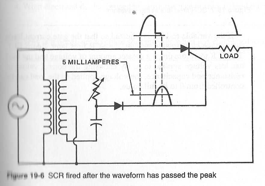
SCR how does it work?
According to my text book this schematic will let you adjust the trigger point on a SCR anywhere in the positive half of the sine wave. But I do not believe this to be true. If I am not mistaken the transformer, cap and varister will shift the gate signal out of phase with the main signal by invtan(1/(r*2*PI*f*C)) degrees. So if r is 0 the phase shift would be 90deg and if R is infinity the phase shift would be 0 degrees. The example show a phase shift of approximately 100 degrees though so I must be interpreting this wrong. Anyone know how it actually works?


Comments
As well, the DC trigger level raises and lowers with the pot so the effect of the shifted wave extends out to 180 deg.
I've not used this particular layout but the effect is the same as a "ramp and pedestal" with cosine modified trigger from the old RCA or GE thyristor manual.
a cap, inductor, and resister is
Xl=2*PI*f*L
Xc=1/(2*PI*f*C)
theta=invtan((Xl-Xc)/R)
theta can be -90 to 90 but if L and C are fixed it can only varry over 90 deg
Silly me over thinking things.
Am I correct?
How about the transformer phasing?