

ModBlade: A new modular prop design (Retro, RepRap, QuadCopter, Arduino alt)
 Cluso99
Posts: 18,071
Cluso99
Posts: 18,071
Postedit 21Oct2010: We have been discussing connectors and micros to do other functions so I have held the design while I rethink.
I have been working on a group of modular boards for quite a while now but due to lack of time they have not yet been completed.
However, I thought I would release a few ideas for feedback/discussion...
ModBlade - My base prop pcb has...
* Propeller 6MHz pluggable xtal (required for USB - 96MHz)
* EEPROM 64K with WE link (enables writing to the eeprom)
* microSD (using P24-27)
* PropPlug header
* miniUSB-AB (for 5V power AND links plus resistors to connect P30-31)
* Reset circuitry (transistor, cap and resistor)
* P0-7 header
* P8-15 header
* P16-23 header
The pcb is smt and comes preassembled and will fit into a Hammond translucent blue case 1551R (2"x2"x0.8").
Power required is 5V regulated and is provided by a user supplied miniUSB cable (for phone or camera). A miniUSB-AB connector is provided on the pcb. Alternately, 5V can also be supplied via a 2pin header.
Each of the three (3) 8 I/O headers are arranged in PMod (TM) style (see www.digilentinc.com) which is a 2x6 RA socket. An additional 2x3 link block allows 5V or 3V3 to be selected for each 4 pin group.
Therefore all the PMod boards from Digilent should work with this prop pcb. These are cheap pcbs. Many FPGA pcbs are using this PMod connection.
I will have some PMod style pcbs too...
* VGA pcb
* TV, stereo out, USB-A (PS2 Keyboard or USB device)
* Gyro, accelerometer, compass and pressure/temp (for Quadcopter)
* Quad Stepper driver (for RepRap project)
* ProtoBoard
* Servo header
* RamBlade II
* RamBlade III
My PMod style pcbs will fit either the Hammond 1551G? (2"x1.4"x0.8") or 1551R (2"x2"x0.8")
The Parallax NES pcb will connect if the power and ground pins are swapped.
One interesting part of this design which I am throwing out here is the SI/SO pins (P31/P30) for downloading. By running preprogrammed code in the eeprom (TBD) which will use Micahs USB code, it should be possible to download code to the prop directly using a standard USB to miniUSB cable (like phones and cameras) as well as power the prop pcb.
This means that we would not require an expensive PropPlug !!!
So, what do we need to do? Well, the eeprom requires a WE link to prevent unwanted writes to protect the code. The eeprom also requires preprogramming (easy for me to do as I do this with RamBlade now). It just needs to boot to microSD where we can select a download program and use the PropTool or bst to download (hopefully no delays required).
Therefore, we need a program that can run the USB connection and download code to the props hub ram and then execute it. This is not quite as simple as it seems as the hub ram will need to be freed up while running USB code. I have not looked yet, but it should be possible to do.
In the interim, we can always download a file to microSD and execute that. Or else, use a PropPlug or a cheap USB to TTL cable (reset circuitry is on my pcb).
I am also using an AV 4posn connector (T/H) for Stereo and TV connections. The connector I am using is quite small and cables/converters are readily available. They can be used for 2 and 3 posn connectors too.
As I have had to buy a large qty of connectors, I will be offering the USB-AB (smt) and the AV4 (t/h) connectors for sale, as well as the 2x8 RA hdr and sockets. I have also purchased 2,3,4,6 position header plugs and both male and female terminal inserts.
Target Audience...
* Retro Emulation
* RepRap & MakerBot (Plastic 3D printer/extruders) www.reprap.org
* QuadCopter
* Arduino alternatives based on www.digilentinc.com PMod TM connections
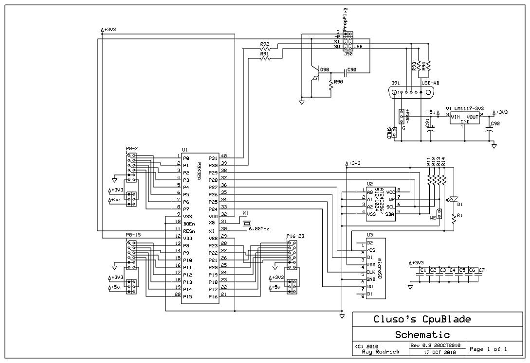
1089 x 747 - 96K
Comments
I have a few targets in mind. One of course is the retro emulations.
However, I have found a couple of areas where the ATmega (& Arduino's) are being used which would be easier with a prop.
One is the QuadCopter project which has slipped a bit due to lack of time, although others such as Jason have it working.
The other is the RepRap project of which the MakerBot is a production version.
My "ModBlade" (the one announced above) plus the Quad Stepper Driver module "StepperBlade" plus another driver module for the extruder heater/temp and platform heater/temp will round out a Prop design for a RepRap.
I have a "micro-mendel" design that I have been working on http://forums.reprap.org/read.php?4,57039 which should be much cheaper to construct. I would love to get the cost down to $250 total but not sure if that can be achieved yet.
For programming the eeprom, you need to short the link. If you fitted the pin header, add a shunt and remove after programming. If you don't have the pin header fitted, a piece of wire poked through the holes CAREFULLY will do.
RamBlade III is not yet fully defined. It is an advanced RamBlade with Prop, EEPROM, microSD, external 5V regulated power via miniUSB-AB (with similar options to ModBlade regarding P31/30). It can operate standalone or plug into ModBlade. SMT components are used and it comes assembled.
StepperBlade is a 4 channel Stepper Motor Driver designed to handle up to ~1.5A. It is designed to drive NEMA 17 Stepper Motors used in RepRap designs. It will drive the X, Y & Z axis and the Extruder (Stepper Motor version). It plugs into ModBlade. SMT components are used and it comes assembled.
SensorBlade has 3-axis chips for Gyro, Accelerometer and Compass, plus Pressure and Temperature. This module is designed for the QuadCopter project and plugs into ModBlade. It can also be used for robots, etc. SMT components are used and it comes assembled.
VgaBlade has the 8 resistors and standard VGA connector. It plugs into ModBlade and adds VGA functionality to ModBlade. ThruHole components are used and will be available unassembled or assembled.
TVBlade has the usual 3 pin resistor circuit for the TV. Two pins are used for Stereo output (an external amp will be required, such as powered speakers). Two AV4 3.5mm connectors are on board. One has stereo output and can have TV linked to this connector also. The second AV4 has TV on the mono sound pin. 3.5mm Mono and stereo adapters to RCA sockets are readily available as are AV cables for Nokia Phones, Camcorders and iPhones. Note AV cables have different pinouts!! In addition, a USB-A is provided which can accept a USB Keyboard (operates in PS2 mode). With appropriate software, such as Micah's USB code, USB devices such as Keyboard, Mouse, Bluetooth, etc maybe connected.
ProtoBlade is just a pcb with the connector and holes to wire a project.
The above expansion modules are specifically designed to fit the Hammond 1551G (2"x1.4"x0.8") case or the Hammond 1551R (2"x2"x0.8") case. (i.e. not both)
For anyone interested in producing pcbs that fit this modular design, here is the VGABlade design which fits a Hammond 1551G case. The pcb is 1.8"x1.2" although 1.75"x1.15" will also work. The scale marks are 0.1", green is the box extremity, pink is the pcb edge. The 2 mounting holes are NPTH 0.120" dia. The modular connector is 2x6 RA pin headers (which I can supply) with pads 0.070" dia and hole 0.040" dia. The pcb mounts on top of the lid between the lid and the box, which expands the height of the box by the thickness of the pcb (1.6mm). This makes it fairly easy to cut the box for any connectors.
Note a box is not necessary, just nice and cheap, and provides protection for the board(s). Boxes are available in translucent blue and translucent red.
I use Protel for my pcb layouts so I cannot post a public format.
Note I have a future feature to interface to the Parallax Dual NES pcb using a cheap Freescale MC9(R)S08 micro. This will be untested and unprogrammed at release and will therefore be optional. I will also be supplying pins and connector housing to rewire (replace) the NES controller plug.
Depending on the Freescale micro used, analog may also be possible.
Postedit: You will note I have allowed for the R&C to ground for the TV connection as suggested by Phil (PhiPi). This corrects the output impedance.
Please keep me up to date on the inexpensive RepRap - I've been meaning to get one...
How big a working area?
Can you please provide a brief specification on board outline, placement, and
connectors so I can transfer the TinyTwoWire schematic to a ModBlade FAB?
Are you including any 4 pin I2C compliant headers on your mainboard?
There will be a header for the I2C (EEPROM) bus per Bill's connection but because it is likely sandwiched between the mini-USB-AB connector (Power & P30/31) and the microSD card there may be an issue without using a cable.
However, I now expect the TVBlade to support the ATTiny84. Two possibilities here...
1. DIP15 and they can buy chip from you and if enough space, I will support 2 x USB/PS2 connections plus the 4xADC or 2xNES connections via a PMod 1x6 or the first 6 pins of the 11-pin prop connector.
2. Provide an I2C (EEPROM) connector for your pcb to plug into.
I can provide you an approx pcb layout for the ATTiny pcb if you would like to do it. Thinking about the pcb, an ATtinyBlade with the connections above (2xUSB-A/PS2, 4xADC/NES connector) and with an 11-pin plug to connect to the prop 11-pin connector and links sto select the I2C pins, plus option for adding the reset/xxxx pins for SPI programming option.
I will think over the next 24 hours - maybe chat on msn?? maybe on in 10+ hours.
It's your circuit and code, so whatever goes is fine by me.
The internet was slow because we were so far out to sea that the cellular connection was poor. My internet uses what we call NextG here. It is rated to 21Mbps but I rarely see much better than about 4Mbps. This is much better than the modems I used to design!
Guess I'll soon be taking a saw to that dust collecting Hydra :devil:
Now if I could only find a good use for that silly memory board.
jazzed: It should not be too difficult to wedge NES into the chip and I am sure I can help with your code if required. I will put the interface on my PCB.
The ATtiny84 will be a good chip for various additions to the prop.