

The ccfl tube inverter that parallax sells, destroyed 32$ in prop chips.
 Clock Loop
Posts: 2,069
Clock Loop
Posts: 2,069
Fair warning to all, as I did NOTHING abnormal when connecting the ccfl tube inverter to my project located here:
http://forums.parallax.com/showthread.php?t=115258
Image of said project with inverter on separate power supply. (you can see red and black wires NOT connected to any power lines the props are using)
http://forums.parallax.com/attachment.php?attachmentid=74270&d=1286483914
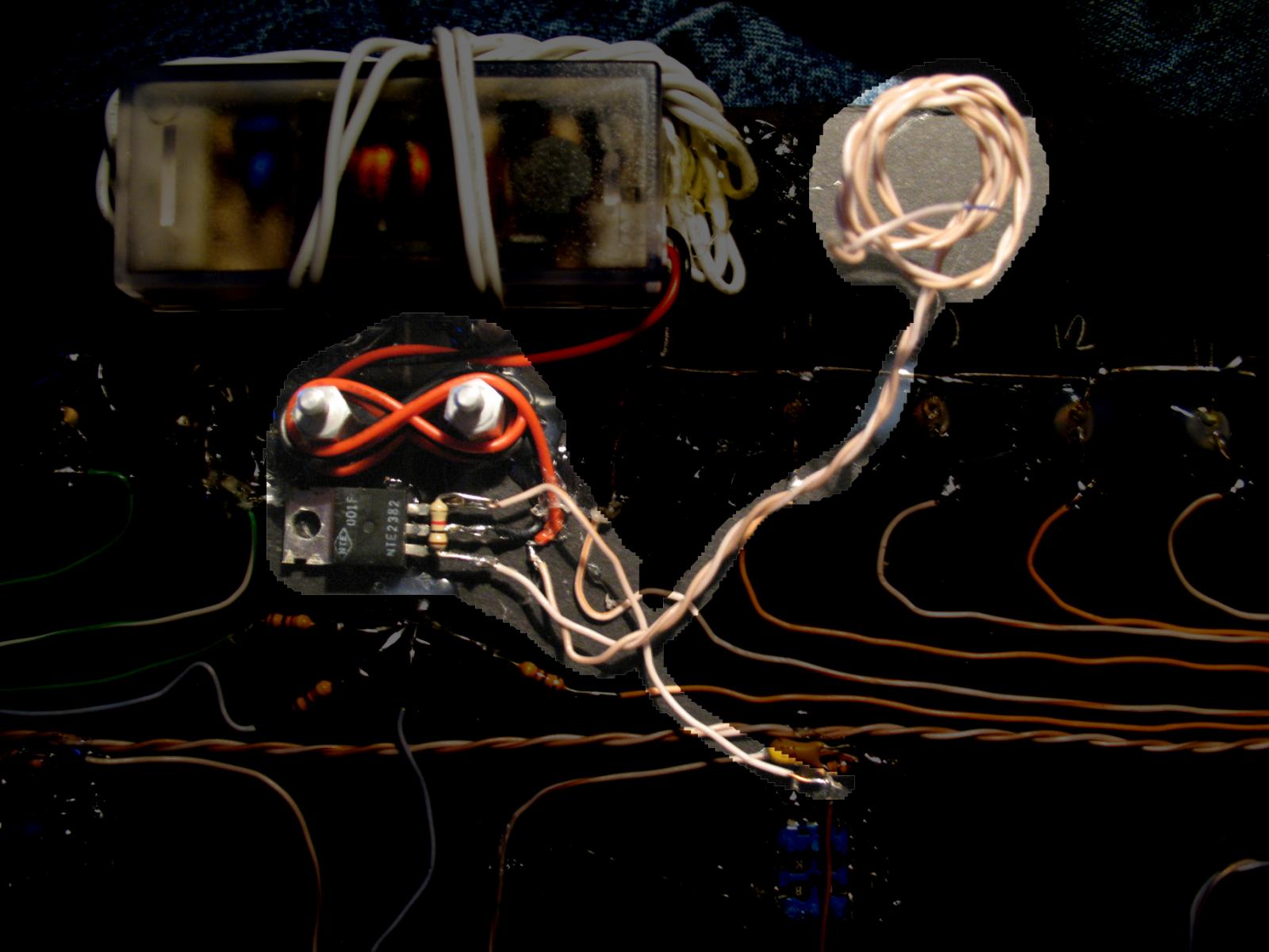
An image of the modification that caused 4 propeller chips to fry instantly when power was applied to whole project is attached below.
Funny thing is that the only connection I had done was to a N-channel mosfet, and power. The power was the same supply as the prop chips. A 12v wall wart. The 12v goes to a 3.3v regulator for the props, and as soon as I soldered the inverter ground, and the + side of the mosfet(the drain), and powered it on, nothing worked. I didn't even turn the gate of the mosfet on yet... as it was not soldered to anything. But I did touch it to the 12v supply to test the ccfl tube operation. I had not even had a chance to connect the gate to a prop. Normally I wouldn't care, but I am unemployed, and 32$ is hard to just burn, plus i figured the ccfl inverter would have at least some protection circuitry??? OUCH! Don't even get me started on how much time it will take for me to replace all 4 prop chips and the eeprom.
Perhaps im missing something I did obviously wrong?
I know isolating high voltage devices is important, but I figured this would have been done in the inverter.
Does anyone have the inverter schematics?
http://forums.parallax.com/showthread.php?t=115258
Image of said project with inverter on separate power supply. (you can see red and black wires NOT connected to any power lines the props are using)
http://forums.parallax.com/attachment.php?attachmentid=74270&d=1286483914
An image of the modification that caused 4 propeller chips to fry instantly when power was applied to whole project is attached below.
Funny thing is that the only connection I had done was to a N-channel mosfet, and power. The power was the same supply as the prop chips. A 12v wall wart. The 12v goes to a 3.3v regulator for the props, and as soon as I soldered the inverter ground, and the + side of the mosfet(the drain), and powered it on, nothing worked. I didn't even turn the gate of the mosfet on yet... as it was not soldered to anything. But I did touch it to the 12v supply to test the ccfl tube operation. I had not even had a chance to connect the gate to a prop. Normally I wouldn't care, but I am unemployed, and 32$ is hard to just burn, plus i figured the ccfl inverter would have at least some protection circuitry??? OUCH! Don't even get me started on how much time it will take for me to replace all 4 prop chips and the eeprom.
Perhaps im missing something I did obviously wrong?
I know isolating high voltage devices is important, but I figured this would have been done in the inverter.
Does anyone have the inverter schematics?
1600 x 1200 - 138K
Comments
Yea,...
Thanks, i don't blame parallax guys for this, i just made a post so no one else makes this mistake. I do realize i should have used a TVS like leon mentioned, or perhaps just keep it on a separate power supply, and do mosfet control via opto isolator..
So far, my experience with prop chips has been so good that i figured I wasn't running a risk.. I have abused them pretty bad in the past, with no issues.
Then again I have never interfaced them with a device (from china?) that supplies 400v AC.....
Reminds me of my time working at a milling machine company doing pcb drive and controller design for 3 phase motors. I am quite familiar with how dangerous 3 phase 400v power is for electronics, but it usually shows up as just problems..., noise....
I was able to solve a problem(that they had for years) with drives blowing up by using a simple TVS to protect the IGBT's. During testing, I was able to save all 6 igbts in the h-bridge 3-phase circuit by using 3 tvs devices.
It was fun testing, forcing a sudden locked rotor, a then watching the TVS devices pop like black cats. Amazingly enough, the igbt's were saved every time. Without the TVS devices, the entire drive would turn into a plastic ejecting, smoke throwing, fire spitting 3-phase MESS.
A common problem we had was that products from china constantly had to be tested for quality and reliability due to the Chinese model of "cost down"
They cut corners until the product is refused by the purchaser, then they apologize, make the corrections, and then try to get away with it again in some other way..
LOL, I don't envy you guys dealing with over seas items.
I am going to replace them all because if three died, the fourth most likely took a hit in the pll or some other sensitive area.
I didn't think the dc side of an inverter was capable of so much carnage. (i mean if correctly designed)
I have used 12v dc to 120v ac (4000hz) inverters with the sx chip and other discreet logic chips before, never had a single issue. Actually I used 3 inverters with a single sx chip to control EL wire. It never once killed my sx chip, and I used that setup for over 5+ years. I used n-channel mosfets also, and had the inverters on the same 12v supply as the sx chip's 5v regulator.
Anyone have suggestions on where to get 3.3v/12v protection circuitry so one COULD use the same power supply for the ccfl inverters?
If parallax intends to get into ccfl tubes and el wire, perhaps they should offer TVS devices or similar? Or give advice/warnings about using protection with these devices on the sales page.
Or even sell the inverters with the TVS/protection already attached/modified.
Bill
I looked up "tvs" which I assume means 'transient voltage suppressor." Does anyone have a suggestion for a part (preferably with Digi-Key part #) to use with these ccfl tubes?
Clock Loop, What the heck kind of contraption needs four Propeller chips? With four Props and CCFL tubes it must be something pretty cool.
Duane
But that would make no sense. Twisting the +12V and control wire together would create too much capacitive coupling between the two and a spike on the control wire when the MOSFET turns on. Plus that skinny little wire providing both the -12V and Vss return would cause a huge ground bounce.
No, I would guess that the MOSFET is miswired and that you've reversed the source and gate connections. That would mean that the twisted pair is your +/-12V supply, which makes more sense. But, in that case, where is the Vss return for the gate circuit?
Also, if indeed the MOSFET gate is to be controlled directly from the Prop, you need to pick a different MOSFET. The NTE2382 has much too high a gate turn-on voltage to be driven from a 3.3V logic signal.
-Phil
It's simply a 3x20 prototype board, with two columns tied together at each row.
NICE PHIL! You are correct in the diagram, except any addition of -12v. There is only +12v and gnd.
I noticed I might have wired it up wrong also, but that made me even more confused on why it all fried. Technically the inverter should have done nothing.
Considering the only power supply I used was a +12v supply, there is no -12v. Only a simple 400ma, +12v DC supply. +12v and gnd.
Now, if in fact I did wire it up wrong, then how the heck did I manage to fry anything? If anything, +12v went into the + side of the inverter, and then due to the mosfet incorrect wiring, it would have never turned on.
If you look at my original post, I never had a chance to connect the gate to a prop output. I figured I might run into the issue of gate voltage, and had a small transistor ready to use, but because the whole thing went BOOM before I could find this out, I never went farther.
I don't doubt that I made a wiring error in wiring up the mosfet, but that makes me even more puzzled on HOW it then managed to fry 4 props.
The only explanation is that the inverter caused a major feedback spike when +12v was applied into the inverter, which then had no where to go, due to no ground, and then responded by throwing out a +400v spike back out the +12v red wire.
Then that means simply the inverter is of crappy design, and needs both a TVS and biasing diodes.
It is pretty cool, it is my "Black Box - HSS audio sequencer that uses LEDS as button"
HERE IS A LINK
http://forums.parallax.com/showthread.php?t=115258
If you look at the first post I made above, the second link is a picture of the device. Also pictures and video are located on the project thread.
I want to know how this happened, because technically it should not have happened, even if I wired up my mosfet wrong.
Thats a pretty good idea.. For me it just means more cost tho(as i have more time than money)
If I had any kind of employment, I would just pcb the darn thing and be done with it.
First, the circuit board shows at D1(diode) is actually a capacitor. (fine, post pcb change...)
Second, where it says PTC (protection thermal fuse) is just a jumper wire. (still, possibly an acceptable omission)
Third, and most important, there are no bias diodes on the dc input. (i understand other components might help prevent HV return spikes, but why not include a device that is made to do just this?) (what it adds a few cents?)
High res pics are attached.
If ANYONE wants to use these inverters, it would be wise to use bias diodes on the DC input, and TVS devices, not even to save your props... JUST TO SAVE YOUR DC POWER SUPPLY FROM HIGH VOLTAGE SPIKES GOING OUT THE DC INPUT. (even if its not connected to anything else, like a prop)
Sorry for the confusion. By "-12V", I meant 12V common. I wanted to be sure to distinguish it from Vss.
But, if my diagram is correct, why would you twist the gate wire together with +12V? That's just asking for trouble, you know, due to the induced transients.
I'm not convinced that that's true. I've driven that inverter from a Prop with no problems. I still think you need to resolve your circuit and wiring issues first (and you do have some) before you can make such a statement.
-Phil
I didn't intentionally twist it like that, i just grabbed a wire that I needed two of. They were already twisted together.
Ok now, comeon.
Transients on the gate of the mosfet won't explain why a voltage spike(big enough to kill 4 props) ended up on the powers supply wires. I understand that your saying that the proper operation of the gate will be subject to issues due to the twisted pair, but were talking about 12v dc, on those wires, Not 400v ac.
(plus the other side of that gate wire was left unconnected) I only once touched it momentarily to the +12v supply to test the operation of the mosfet and inverter. (and i don't think it even worked)
Not sure if you noticed, but if using twisted pair like that caused massive voltage spikes with simple 12v dc, I would have had issues years ago. I have been wirring up projects like this for years, and found that in most cases, twisted pair its not an issue. (unless were talking about PRECISE gate control, like your focusing on)
Look at these images, and tell me, how many wires do you see with twisted pair?
These wiring jobs are a FRIGGIN MESS, and in your train of thought would be a total nightmare for props, due to the TRANSIENTS induced in the other wires.(yes this project totally screws up DTV, even in the other room, no doubt it throws off total chaos when it comes to EMI)
But every one of those pictures is of a device in perfect operation, to this day. (but yet if you study my program and design, many of those wires have 250kbps serial data going through it, and work fine)
http://forums.parallax.com/attachment.php?attachmentid=74270&d=1286483914
http://forums.parallax.com/attachment.php?attachmentid=62967&d=1250418003
http://forums.parallax.com/attachment.php?attachmentid=68139&d=1267278411
But your focusing on the gate being subject to transients, when you mention that the darn thing wouldn't have even worked anyway due to the way its wired up? Moot point.
Lets talk about how the inverter managed to cause such a high voltage spike when apparently the mosfet wasn't even wired correctly?
Lets talk about how the inverter could have even caused such a high voltage spike OUT THE DC INPUT in the first place.
FORGET the damn gate noise... If my issue was how my mosfet wasn't operating properly, then I would humor you, but....
The whole reason this post was started was because the inverter managed to blow up 4 props, due to some kind of spike that came out the DC supply side of the inverter.
From my experience, thats due to bad push pull inversion design.
I can humor you, by setting up a test rig, with 12v dc PUSLING to a mosfet gate, TWISTED with a 3.3v serial line(or power), and show that no prop will EVER BLOW UP. (worst case, the serial data gets all garbled, or a prop may reset)
I don't deny that I might have done some dumb things, but the dumb things I did do, DON'T REALLY EXPLAIN how 4 props would fry in this situation. The only explanation is that my dumb things COMBINED with bad inverter design caused a major voltage spike to come out the inverter.
In that case, a simple bad connection with ground would do the same thing, even to your inverter setup due to, a bad inverter design.
So then technically for anyone to blow up their prop, all one would need to do with this inverter, is lift the ground erratically and eventually one would see massive voltage spikes out the +12v dc wire, which would most definetly kill a prop.
No incorrect mosfet wiring would be needed (or noise on the gate) (or gate twisted pair) to kill a prop.
The first order of business here is to eliminate as many variables as possible. So is the MOSFET wired correctly? You say it is, which means the gate line is twisted together with the +12V line. Okay, if that's the case, there's still that skinny little wire connecting both the 12V return and Vss to the MOSFET's source. That's is a problem. Vss and the 12V return need to be joined at the MOSFET, not at some remote location. IOW, you need two wires feeding the source pin: one from Vss and one from the 12V supply return. This will prevent heavy currents from flowing in the Vss circuit.
Now, if you're regulating the 12V down to 3.3V for the Prop, you won't be able to separate Vss and the 12V return like this, because they're the same. In that case, just make sure that the MOSFET source is connected at the 12V supply terminals and not somewhere that would cause inverter return currents to flow through your logic circuitry.
As I said: I've controlled these inverters from the Prop without a problem. There's nothing crappy about the inverter design that would cause the kinds of problems you're seeing, given a sound design and wiring. You need to look first at your implementation for the cause of your problems and tighten things up there before you can blame the inverter.
-Phil
I fully respect your analysis of the situation, your very smart, as shown in your many posts and support here.
I totally agree, the pull down resistor is why the gate isn't an issue here. There is something else going on, this is why talking about the mosfet in any capacity is a moot point.
I think whats going on here, is when 12+ power was applied to the circuit, it raced through the inverter, had no where to go, then came back out the 12v+ lead of the inverter into the supply, crossed over the 3.3v regulator(due to such high voltage spike) which then fried the props. Or even just jumped the mosfet circuitry into vss. Or all the above.
Basically the inverter caused a massive voltage spike on the DC leads, one that could have prevented if the inverter had some components that are for exactly this situation.
I doubt it is wired properly, i can test it, to see if the inverter will light up, as I have not changed anything since it all blew up (except for the removal of all prop chips) But i don't think that this is what caused the props to fry.
The gate line is twisted with the +12v line.
All wires, VSS and 12v and the gate have the same size wires. The wires are not much different than the size that the inverter comes with for the DC supply.
Due to the speed of electrons through copper, and the amount of current were talking about here, plus the distances the wires travel, I think this point is without merit (unless were talking about RF)
Why would any return flow through a more resistive path(a prop), than through copper directly connected to the gnd of the 12v supply?
I challenge you. Take that inverter, and erratically lift the ground, when your prop is connected to the same 12v supply using a 3.3v regulator.
High voltage spikes will probably show up on the 12v side, travel through the 3.3v regulator, and kill your props.
Or just take a mosfet and wire it the same way I did, and see what happens. I just don't think its the mosfet wiring job that did it. I think its some kinda transient that came out the 12+v DC side of the inverter.
Heck i suppose technically it could have come out either side of the inverter, VSS or 12v.... Because a 400v spike out either side of the dc supply side of the inverter would cross any electronic junction, mosfet or regulator, and plow its way through the prop circuitry.
You can keep using this inverter with your prop, but I will not be doing this, at least not without more protective circuitry.
Perhaps one day when I feel like it, I will rev engineer the inverter circuit, and show exactly why its a bad design.
(using my knowledge of 3-phase brushless motor drive design)
But for now I am not really going to talk about this anymore due to it being such a wierd situation, with my crappy wiring job.
I am only trying to make the point that if anyone wants to use this inverter, due to the limited amount of protection components involved in the inverter circuit, it would be dumb for anyone to not protect or isolate this device from any logic circuitry, basically the same point that LEON made on the second post.
But I give up. You obviously think you have the answers, and I've done all I can with the information available. You're on your own. The tragedy is that I'm very certain that the inverter has been unfairly disparaged.
-Phil
I do agree with you on the fact that the inverter would need a complete circuit to do its deed, but what about the capacitors, they do hold charge
Thanks for your effort in dealing with such a moron like myself(i am a moron quite often), it must obviously be my mosfet wiring job. This means I created a really neat chip buster..
I should try to replicate it. (no need for the inverter, right?, i just need an incorrectly wired mosfet with its gate connected to a twisted pair wire that its + supply feeds through?)
I think we both need to chill out, and accept this as being an odd situation combined with unknowns.
My experimental wiring sometimes looks like yours, with the same advantages and disadvantages: the temptation to get quick results against the risk of blowing up expensive kit.
Whether working with wire jumpers, breadboard or real PCB's, I have wasted weeks and literally thousands of pounds of my own money trying to fault the test/first batch of kit instead of proceeding more slowly, carefully and neatly in the first place. I usually get away with it, which makes for very economic development/shipping/invoicing but sometimes I don't and the consequences can be expensive.
For rush jobs, one project manager used to team me up with the most maddenly careful and precise engineer: separately, I would always meet the deadline but with every shortcut taken; my mate would only ship the most fabulous kit but weeks late. Together we were brilliant!
Another one of my faults is in looking backwards, from my failed design, rather than forwards, from a known solution.
Phil Pilgrim's analysis is a model of wise advice ...
Regards,
T o n y