Poor Man's BS1 Slow Scan Camera
 erco
Posts: 20,263
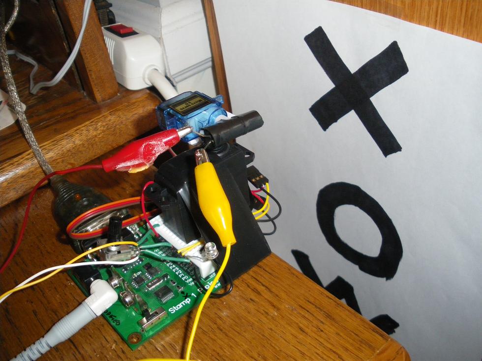
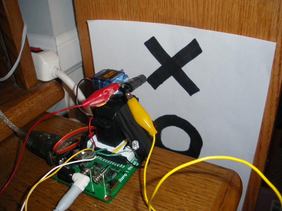
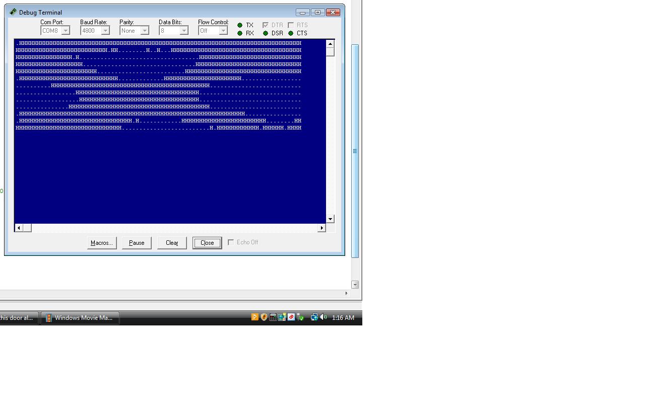
Just got the first results from my homemade minimalist BS1 Camera. It manually scans an image with 2 servos doing a painfully slow XY scan of a phototransistor in a black tube. The ptx is in a voltage divider arrangement with a carefully-adjusted 100K pot to yield voltages near the Stamp's 1.4V low/high transition voltage, so the simple software just sees black or white, and indicates high/low on a status LED for adjustment. Of course the BS1 memory is too small to hold the image (heck, a tiny program barely fits in there) so I use the DEBUG screen to display the image. The attached screen shot shows my debug screen displaying a scan of the big black X shown in the setup. Outlying points show up dark since the angle gets big around the edges.
Clearly there is room for improvement; the pot adjustment is quite sensitive, and even lighting is critical for even modest results. Using the POT command or a BS2 and a lens would all be steps in the right direction. But this shows my BASIC idea using just a handful of parts: a BS1 project board, 2 servos, a phototransistor, a pot and an LED. Neither hi-res nor incredibly useful, but it shows what this country boy can do when I come up with another hair-brained poor man's concept.
Clearly there is room for improvement; the pot adjustment is quite sensitive, and even lighting is critical for even modest results. Using the POT command or a BS2 and a lens would all be steps in the right direction. But this shows my BASIC idea using just a handful of parts: a BS1 project board, 2 servos, a phototransistor, a pot and an LED. Neither hi-res nor incredibly useful, but it shows what this country boy can do when I come up with another hair-brained poor man's concept.


Comments
Erco, how long you've been playing with BS1 ?
Amaral
What makes it even slower is that I goofed when I used a digital servo. My first time, I just grabbed it out my overflowing servo drawer. I THOUGHT it would behave just like an analog servo, and it did in some early testing. So I built my rig and wrote the code like pulsout servo x, pulsout servo y, test pin hi/lo, debug output, repeat. But that BS1 DEBUG delay is apparently MUCH longer than the 20 ms servo pause. The digital servo just stops responding, some kinda timeout. So I had to add loops to send 3 consecutive pulsouts to each servo before the Debug statement. That slows down the whole process.
Live & learn!
Yeah, it's not a real practical application, just fun to try; I just like to maximize my bang for the buck. The BS1 is still plenty good for many apps!