

Driving a 3W RGB LED from various voltages
 John M Bond
Posts: 29
John M Bond
Posts: 29
Hi Guys
I would like to drive a 3Watt RGB LED using an SX28. I will use 3 PWM signals to give 6 colours, and the option to flash them if I need to. (This is an indicator column lamp on a production machine. Green=Run, Red=Stop for quality, Yellow=Machine Breakdown, Blue=No Parts or Line full, White=No Operator, Purple=Machine idle. You can get combinations, for example the machine may be running but short of parts, Flash green/Blue. This is a TPS-Andon system required by Japanese Auto makers before they will buy auto parts from an OEM manufacturer)
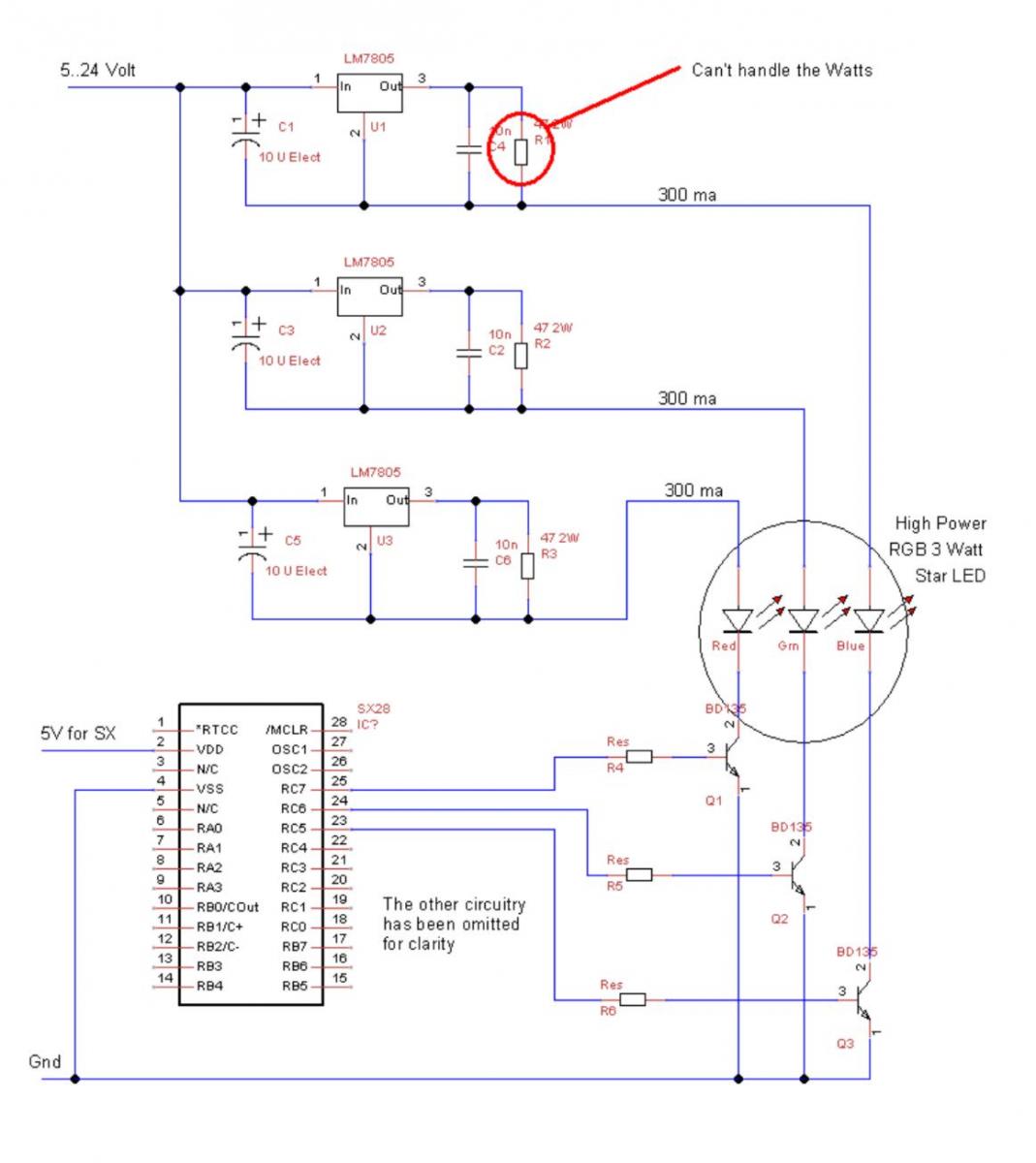
The problem is that the LED could be fed with any voltage 5..24V (depending on the machine it is fitted to).
I can hack the system and supply the LEDs via resistors from the supply for the SX but I am wondering if there is a simple circuit to limit current than can be switched by an SX (or Stamp). I want this to be fairly generic because I may have to fit 10 or 15 units to different types of machines.
Attached is my first go using 7805 regulators. I missed the fact that the limiting resistor would handle the full current at the full voltage less the LED voltage. At 24 volts, the dissipation is a lot of watts and a lot of heat. The other problem is the regulator drops out at the LED voltage + about 5 volts. This means a minimum supply voltage of about 9V.
Is there a simple circuit to control milliamps regardless of voltage? It doesnt matter if the current climbs 10% as voltage goes up because I am driving the LED well below Spec (Because like much Chinese stuff, there is no printed spec for these LEDs!!!)
Kind regards from Darkest Africa this cold and stormy night (60 Deg F is cold for us).
John Bond
Edit - Modicon have sent me the RGB LED Spec Sheet - I've attached it!!!
I would like to drive a 3Watt RGB LED using an SX28. I will use 3 PWM signals to give 6 colours, and the option to flash them if I need to. (This is an indicator column lamp on a production machine. Green=Run, Red=Stop for quality, Yellow=Machine Breakdown, Blue=No Parts or Line full, White=No Operator, Purple=Machine idle. You can get combinations, for example the machine may be running but short of parts, Flash green/Blue. This is a TPS-Andon system required by Japanese Auto makers before they will buy auto parts from an OEM manufacturer)
The problem is that the LED could be fed with any voltage 5..24V (depending on the machine it is fitted to).
I can hack the system and supply the LEDs via resistors from the supply for the SX but I am wondering if there is a simple circuit to limit current than can be switched by an SX (or Stamp). I want this to be fairly generic because I may have to fit 10 or 15 units to different types of machines.
Attached is my first go using 7805 regulators. I missed the fact that the limiting resistor would handle the full current at the full voltage less the LED voltage. At 24 volts, the dissipation is a lot of watts and a lot of heat. The other problem is the regulator drops out at the LED voltage + about 5 volts. This means a minimum supply voltage of about 9V.
Is there a simple circuit to control milliamps regardless of voltage? It doesnt matter if the current climbs 10% as voltage goes up because I am driving the LED well below Spec (Because like much Chinese stuff, there is no printed spec for these LEDs!!!)
Kind regards from Darkest Africa this cold and stormy night (60 Deg F is cold for us).
John Bond
Edit - Modicon have sent me the RGB LED Spec Sheet - I've attached it!!!
1069 x 1200 - 84K
pdf
460K
Comments
AP1501-50T5L-U would be simple to use and will take input voltages from 7 to 40V.
If you want 5V+ as input you will need to use a buck/boost system which is more expensive.
by the way that is not the proper way to hook up a 7805.
Remember I want to control current, not voltage. This is the way shown in the application notes for both 7805 and LM317 for use as current regulators, and it seems to work quite well, except for the heat and the voltage limitations. It limits the current through the resistor by controlling the voltage drop across the resistor (5V for 7805, 1.25 for LM317 very ingenious). There is also a small current flow out the ADJ pin (5ma I think).
I've seen a circuit somewhere using two transistors that gives a fair current limiting performance. That is just what I am looking for.
If all else fails, Ill get out my hacksaw, tin snips and Stanley knife...
There are many ways to limit current flow to a diode. most switching regulator ICs have an internal current limiting circuitry which will automatically limit the current. However this circuitry is designed to protect the chip and not your devices and is designed at a set current and not a variable current.
Using a switching regulator to provide you with a known good voltage would be the easiest since then you can just use small series resisters to drop the excess voltage and to limit the current to the power the LED needs.
Something like this would probably work for you also -
http://www.dimensionengineering.com/DE-SWADJ3.htm
Can these be adjusted in the field, or does it need to be plug and play? You could ditch the 7805's and use resistors only, and adjust your pwm to match the wattage.
Really though, if you can build up your own deal, I'd say go with something down this line -
http://www.onsemi.com/PowerSolutions/product.do?id=CAT4201TD-GT3
Although this requires voltage 3 volts above led forward voltage. Can you budge on that 5v requirement? The broad range requirement is a bit of trouble.
That way you don't have to deal with any power dissipation.
Kwinn - That circuit looks interesting. I don't know enough about electronics to calculate Ri but I'll work it out experimentally.
Erik. Thanks for your input. If I can't adapt The Transistor/Diode circuit. I'll take your advice and use the HV9910B which is available in South Africa. It only goes down to 8v but can handle up to 450V!!! The circuit's a bit more complex, about 8 components. The ZXLD1360 is also available, at about the same price but it's SMD:mad:
Thanks again guys for your help
Keep in mind the transistor power dissipation at 24V in would be:
24 – (led forward voltage drop + resistor voltage drop) x I
I would include at least a 50% safety margin in the power dissipation calculations.
At 350mA and 24V the power dissipation would be:
Ri - 0.7 x 0.35 = 0.245W
Q1 - (24 – 2.9) x 0.35 = 7.39W
A ½ watt resistor would be fine for Ri, but the transistor needs to be rated at 10W or higher, and would need to have a heat sink as well.
I'd found that the resistor and transistor GOT HOT. It works well...
The small resistor I used turned black and burned my breadboard!!!
Thanks for the calculations. I'd used a 2.7 Ohm 1/4W out my junk box. I missed the transistor power dissipation and would have used too small a transistor. What's interesting is that the unit will dissipate less than the 24 Volt 11 watt incandescent bulb. 24V is used in about half the units. The dissipation will be much less on the 12 Volt units.
This little circuit (X3) will fit easy into the large bases of the Japanese tower lamps and will be a breeze on the bigger German units. (Of course the British have to be different, they have no base but there is only one Brit unit).
While writing this, it occurs to me that if I go SMD, I can probably get the SX, 9 opto couplers (for the inputs), this circuit (x3) and a suitable power supply into each bases. That would truly make the unit "Generic". The electrician would mount the modified unit exactly the same way he does the existing filament unit. Africa has a terrible lack of skills - maybe all our skilled people are those illegal immigrants living in Europe and the USA.:smhair:
Please post a picture of the finished product if you can. I am always curious to see how these projects turn out.
It turned out much better than I expected.
The project is a work in progress and will be modified extensively over the next months and prototypes. The photo is current state of play.
The LED lamp is absolutely AMAZING!!! I would guess it is about as bright as a 20W incandescent bulb but you can choose and vary the colour, hue and flash it is the most amazing toy. FAR TOO GOOD FOR MY HUMBLE FACTORY CONTROL.
For those wanting bio-feedback, entrainment is easy. I started getting very edgy at 3am this morning, flash rate about 16 Hz in moving colours. Quite disturbing.
Also good for entertainment. Think of automotive signal indicators that occasionally randomly give off a flash the wrong colour and other oddball and stupid ideas.
(Did you say my car's indicator flashed purple, have you gone mad!! Now you claiming you just saw a single blue flash, it's time to take you off to the madhouse...)
The photos don't do the device justice. The rich colours are AMAZING
Thanks again...