

Propeller Backpack-based Antenna Analyzer
 Phil Pilgrim (PhiPi)
Posts: 23,514
Phil Pilgrim (PhiPi)
Posts: 23,514
Effective wireless communication starts and ends with a good antenna. So, in order to maximize the performance of any wireless device, the antenna must be tuned for its best performance, too. This post describes a device that I built using the Propeller Backpack that analyzes the performance of 50-ohm radio antennas over a 0.1 - 30 MHz frequency range (or any subrange or single frequency within those bounds).
When an antenna's characteristic impedance at a given frequency matches that of the circuit driving it, the maximum amount of power will be transferred to the antenna and radiated as RF. This condition depends on many factors, including the effective length(s) of the radiating elements(s), the lenght of any counterpoise involved, and the antenna's height above ground. A typical amateur radio transmitter has a characteristic output impedance of 50 ohms. So the objective will be to make sure that the antenna also exhibits a 50-ohm impedance at the frequency of interest.
In order to measure the performance of my antennas at 50 ohms, I built a "return loss bridge", which basically consists of some resistors and an RF transformer. Here's a schematic (adapted from the ARRL's Experimental Methods in RF Design, Revised First Edition, Fig. 7.41):
It should be clear from the schematic that, if a 50-ohm resistor were placed across the antenna output, the bridge would be in balance, and the bridge output voltage would be zero at all input frequencies. At any other impedance on the antenna terminals, the bridge would be out of balance and an output would register across the bridge. By connecting a real antenna and measuring the bridge output at various excitation frequencies, one can obtain a graph of the antenna's "goodness of match" across the chosen frequency range.
I built my return loss bridge on a Parallax Proto-DB, which plugs into the Propeller Backpack. Here's a full schematic:
The bridge excitation comes from a square-wave counter output (NCO or PLL, depending on frequency) applied to A3. A4 is held at ground potential, thus creating a divider with a 50-ohm characteristic impedance and a 1.67V peak-to-peak output. This signal is capacitivley coupled to the bridge. The output of the bridge is capacitively coupled to a clamp circuit (DC restorer), consisting of a 1.2V regulated supply and a diode. The clamp ensures that the negative-going tips of the bridge output waveform are held at 0.6V (1.2V regulator - 0.6V diode Vfwd), so the positive differential can be measured. The clamped output feeds back to the Backpack's delta-sigma ADC for measurement.
Lest there be any concern about RFI (radio frequency interference) from this device, the output power to the antenna (as measured on my oscilloscope) came to a mere 1.8 mW RMS. Moreover, the output at any single frequency during a sweep is limited to no more than 30 milliseconds.
Here's a photo of the completed system:
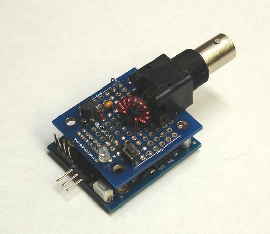
Of particular note is the RF transformer, which was wound "bifilar" style on a ferrite torroid. In this method of coil construction, the two windings are wound as one with a pair of wires lying side-by-side. This helps to minimize any common-mode response from the transformer, so that only the differential mode response gets measured.
Since the square wave output consists of odd harmonics of the fundamental signal, I take two measurments at each frequency: one at the fundamental and another at three times the fundamental. A portion of the output from the second measurement is subtracted from the first measurment to approximate more closely the bridge response from a sine wave at the fundamental frequency. The constant of proportionality was determined empirically, starting at 1/3 and working down until no negative values resulted.
A complete antenna analysis consists or two parts: a calibration across the spectrum without the antenna connected, and a similar set of measurements with the antenna connected. At each frequency, the voltage reflection coefficient, or gamma (Γ) can then be calculated as:
A value related to gamma is known as the return loss (RL), and is calculated as:
Finally, another term more familiar to radio amateurs, the voltage standing wave ratio, or VSWR may be computed as:
A VSWR of 1.0 (i.e. |Γ| = 0) represents a perfect match.
To put my antenna analyzer ot the test, I tuned a BuddiStick vertical antenna to 7025 KHz in the 40-meter band using a low power transceiver and a RadioShack SWR meter. Then I connected the coax feeder, sans antenna, to the analyzer and did a calibration. Finally, with the antenna connected, I took another set of readings and plotted them in Microsoft Excel. Here's the top-level program listing for the analysis phase:
Here's the graph from Excel of gamma vs. frequency:
Next, I did a more detailed analysis centered on the 40-meter ham band (7000 - 7300 KHz) and plotted the VSWR. (The program for this is included in the attached archive.) Here's the plot:
Although the position of minimum VSWR agreed quite well with that of the RadioShack SWR meter, the SWR meter produced much higher readings off resonance than did my analyzer. I'm not quite sure of the reason for this. Perhaps someone with more RF experience could shed some light here.
It's also possible to use the analyzer to aid in tuning an antenna to a specific frequency. In order to do this, I took advantage of the Backpack's audio output capability and created a tone whose frequency is proportional to (VSWR - 1) at the frequency of interest. By connecting the audio output to an amplified speaker, it is possible to tune the antenna and its counterpoise while it's being continuously analyzed, adjusting it for the lowest audio frequency. The "squealer" program for doing this is also included in the attached archive.
With the Backpack's video output capability, it should also be possible to plot the gamma or VSWR curves directly onto a TV screen. For me, however, the squealer is probably the most useful aspect of this system. It's portable and makes antenna tuning in the field much easier than running back and forth between the antenna's loading coil or adjustable counterpoise (in my case a steel tape measure) and an SWR meter for each little tweak, until you're sure things are optimized.
-Phil
When an antenna's characteristic impedance at a given frequency matches that of the circuit driving it, the maximum amount of power will be transferred to the antenna and radiated as RF. This condition depends on many factors, including the effective length(s) of the radiating elements(s), the lenght of any counterpoise involved, and the antenna's height above ground. A typical amateur radio transmitter has a characteristic output impedance of 50 ohms. So the objective will be to make sure that the antenna also exhibits a 50-ohm impedance at the frequency of interest.
In order to measure the performance of my antennas at 50 ohms, I built a "return loss bridge", which basically consists of some resistors and an RF transformer. Here's a schematic (adapted from the ARRL's Experimental Methods in RF Design, Revised First Edition, Fig. 7.41):
It should be clear from the schematic that, if a 50-ohm resistor were placed across the antenna output, the bridge would be in balance, and the bridge output voltage would be zero at all input frequencies. At any other impedance on the antenna terminals, the bridge would be out of balance and an output would register across the bridge. By connecting a real antenna and measuring the bridge output at various excitation frequencies, one can obtain a graph of the antenna's "goodness of match" across the chosen frequency range.
I built my return loss bridge on a Parallax Proto-DB, which plugs into the Propeller Backpack. Here's a full schematic:
The bridge excitation comes from a square-wave counter output (NCO or PLL, depending on frequency) applied to A3. A4 is held at ground potential, thus creating a divider with a 50-ohm characteristic impedance and a 1.67V peak-to-peak output. This signal is capacitivley coupled to the bridge. The output of the bridge is capacitively coupled to a clamp circuit (DC restorer), consisting of a 1.2V regulated supply and a diode. The clamp ensures that the negative-going tips of the bridge output waveform are held at 0.6V (1.2V regulator - 0.6V diode Vfwd), so the positive differential can be measured. The clamped output feeds back to the Backpack's delta-sigma ADC for measurement.
Lest there be any concern about RFI (radio frequency interference) from this device, the output power to the antenna (as measured on my oscilloscope) came to a mere 1.8 mW RMS. Moreover, the output at any single frequency during a sweep is limited to no more than 30 milliseconds.
Here's a photo of the completed system:
Of particular note is the RF transformer, which was wound "bifilar" style on a ferrite torroid. In this method of coil construction, the two windings are wound as one with a pair of wires lying side-by-side. This helps to minimize any common-mode response from the transformer, so that only the differential mode response gets measured.
Since the square wave output consists of odd harmonics of the fundamental signal, I take two measurments at each frequency: one at the fundamental and another at three times the fundamental. A portion of the output from the second measurement is subtracted from the first measurment to approximate more closely the bridge response from a sine wave at the fundamental frequency. The constant of proportionality was determined empirically, starting at 1/3 and working down until no negative values resulted.
A complete antenna analysis consists or two parts: a calibration across the spectrum without the antenna connected, and a similar set of measurements with the antenna connected. At each frequency, the voltage reflection coefficient, or gamma (Γ) can then be calculated as:
Γ = Vloaded / Vopen
A value related to gamma is known as the return loss (RL), and is calculated as:
RL = -20 log(Γ)
Finally, another term more familiar to radio amateurs, the voltage standing wave ratio, or VSWR may be computed as:
VSWR = (1 + |Γ|) / (1 - |Γ|)
A VSWR of 1.0 (i.e. |Γ| = 0) represents a perfect match.
To put my antenna analyzer ot the test, I tuned a BuddiStick vertical antenna to 7025 KHz in the 40-meter band using a low power transceiver and a RadioShack SWR meter. Then I connected the coax feeder, sans antenna, to the analyzer and did a calibration. Finally, with the antenna connected, I took another set of readings and plotted them in Microsoft Excel. Here's the top-level program listing for the analysis phase:
CON

  _clkmode      = xtal1 + pll8x
  _xinfreq      = 10_000_000

OBJ

  ant   :       "antenna_analyzer"
  sio   :       "FullDuplexSerial"
  fst   :       "FloatString"

PUB start | i, freq

  ant.start
  sio.start(31, 30, 0, 9600)
  'ant.calibrate                 'Uncomment for calibration.
  'ant.save_calibration(1)       '
  'repeat                        '
  ant.load_calibration(1)
  repeat i from 1 to 300
    freq := i * 100_000
    sio.dec(freq / 1000)
    sio.tx(",")
    sio.str(fst.floattostring(ant.gamma(freq)))
    sio.tx(13)
Incidentally, this is the first time that I've ever used floating point math with the Prop. It's hardly ever necessary, but it was a big help here.Here's the graph from Excel of gamma vs. frequency:
Next, I did a more detailed analysis centered on the 40-meter ham band (7000 - 7300 KHz) and plotted the VSWR. (The program for this is included in the attached archive.) Here's the plot:
Although the position of minimum VSWR agreed quite well with that of the RadioShack SWR meter, the SWR meter produced much higher readings off resonance than did my analyzer. I'm not quite sure of the reason for this. Perhaps someone with more RF experience could shed some light here.
It's also possible to use the analyzer to aid in tuning an antenna to a specific frequency. In order to do this, I took advantage of the Backpack's audio output capability and created a tone whose frequency is proportional to (VSWR - 1) at the frequency of interest. By connecting the audio output to an amplified speaker, it is possible to tune the antenna and its counterpoise while it's being continuously analyzed, adjusting it for the lowest audio frequency. The "squealer" program for doing this is also included in the attached archive.
With the Backpack's video output capability, it should also be possible to plot the gamma or VSWR curves directly onto a TV screen. For me, however, the squealer is probably the most useful aspect of this system. It's portable and makes antenna tuning in the field much easier than running back and forth between the antenna's loading coil or adjustable counterpoise (in my case a steel tape measure) and an SWR meter for each little tweak, until you're sure things are optimized.
-Phil

360 x 267 - 2K

533 x 500 - 5K

531 x 460 - 33K

648 x 444 - 5K

648 x 444 - 4K

Comments
Thanks again!
I had to stare at the arrangement with the bifilar xfmr quite a while before it became clear, well, clear but still pretty fuzzy. 1) The EMF produced on the secondary (antenna side) of the xfmr is equal to the EMF across the primary side 50Ω. 2) That is added to the voltage present at the antenna node. 3) The wiring sense of the transformer is such that the two EMFs add up to zero at the "bridge output" when the antenna is 50Ω resistance, so 0% reflected. Okay so far? If the antenna is short circuited, then only the primary voltage is present, so call that 100% reflected. And if the antenna is open, it is 2*V - V = V, so again 100% reflected.
How do you figure,
Γ = Vloaded / Vopen
Shouldn't that be comparing the value with a perfect 50Ω load to the value with the DUT antenna connected?
Then, the DC restorer. The way I understand you is that the waveform presented to the ADC then the "bridge output" offset so that the lowest point on the waveform is about 0.6Volt? But still at the original input frequency. Is the soft knee of the diode a problem?
The voltage Vrev is compared with the forward voltage Vfwd. Vrev=0 when the load is R ohms resistive, and if Z is either open or shorted, Vrev=Vfwd. Here is how diodes can detect the two voltages:
One advantage of this circuit is that with proper choice of components and good construction it can have very wideband performance. <http://www.ludens.cl/Electron/swr/swr.html> is one good web reference on how the circuit works and how to build it.
Here is my own crude try at it. Note that there can't be any DC offset in the input waveform. Correct operation does depend on that, so if the input comes from a Prop pin it does need the coupling capacitor as in Phil's implementation. Now I have to take Phil's lead and hook it up to ADCs!
That's all I know.
Yes to both questions. The latter is the reason I made the "A4" connection to the Prop and not to ground. My objective was to excite the bridge with both A3 and A4 at once, thus doubling the input voltage, so I could calibrate out the diode's "knee" effect. But "good enough" trumped "better", and I never got around to it.
_______
Tracy, on your fwd/rev bridge, I assume you have to add the diodes' forward voltage before taking a ratio, right? I've seen similar circuits, but I was hesitant to use one that required enough excitation of a radiating antenna to render the diode losses moot -- especially at frequencies where I'm not licensed.
-Phil
The diode voltage may be negligible. In the detector circuit, given time enough, the diode continues to conduct in the forward direction through an ever increasing dynamic resistance, until the forward current balances the reverse current plus whatever is drawn by the measurement voltmeter. In the case of a good RF diode and a high input impedance meter, the voltage offset can be well under 0.1 Volt. Particularly with a good Schottky diode, reverse current of 10 or 20 nA. There is a tradeoff though between settling time and accuracy.
Another approach would be to measure the capacitor voltages directly with a high impedance differential ADC as follows:
p = Vrev / Vfwd
swr = (1+p) / (1-p)
Two direct measurements allow computation of the ratio without having to disconnect the "Z". Rapid scanning would require a trick to reduce the settling time.
You (and ARRL of course) are right. I had not absorbed what I had just said. I'm truly hazy and feeling my way with this stuff too.
I'm still confused about the the sequential calibration procedure. Calibration of your system is done without the antenna load, to determine V0 vs frequency. However, when the antenna or load is subsequently connected, the EMF at the top of the bridge will drop due to the output resistance of the Prop driving circuit (100Ω / 2 + Prop output resistance). For example, when the antenna load goes from open circuit to short circuit, the total bridge impedance drops from 100Ω down to 33Ω and that changes V0 substantially, and it will fluctuate with frequency for a reactive load. I've just started studying your antenna analyzer spin code, but I don't think there is compensation for that in there. I could be way off base on my analysis of course, and maybe that compensation is not necessary after all. But why?
In the dual diode detector, the two EMFs for the ratio are measured simultaneously under the loaded condition, so the driving impedance is not a factor. But due to that issue, I think the two methods would give different results.
Thank you for that Spin code and the whole project by the way. Please do not take my comments as sniping, rather, curiousity!
I really appreciate your probing! Hopefully it will help to clear the fog that I'm still in over this stuff.
Now that I've read your analysis and reread the section in the ARRL book, it appears I may have misinterpreted the requirements for the bridge excitation. My initial assumption was that this input had to have a 50-ohm source impedance. That's the reason for the two 100-ohm resistors. But now I wonder if the two 50-ohm resistors in the upper arm are meant to determine the source impedance for each arm, given a 0-ohm signal source. IOW, the net 50-ohm load impedance of a balanced bridge was a red herring, lulling me into thinking I had to match that impedance at the source.
Another possible issue is the load impedance of the sensor which, in my case, is about 1K. For other bridges discussed in the same chapter, the author mentions using a 50-ohm-terminated scope probe to measure the output.
I was hoping to avoid the necessity for current amplification at the source end or voltage amplification at the sensor end. It now appears that, for accurate readings, I may need both. OTOH, it does provide useful information as-is, which agrees with the other SWR meter -- at least relatively.
Pursuant to this issue and the one concerning the diode knee, I've attached scope traces from three termination situations, taken at the DC-restoration node. As you suspected, the output from a shorted load is less than that of an open load. (Theoretically, they should be the same.) Also, comparing the open and terminated traces, the effect of the diode knee looks to be ~70 mV.
-Phil
I am not very familiar with winding my own inductors - I have a number of ferrite toroids lying around - does it make a huge difference what kind I use in something like this? My toroids are slightly larger than the one in your photo.
I'm sure other toroids will work just as well. You may want to look up the specs for the one I used (FT37-43) and match it as close as you can from those that you have. If you're serious about RF experimenting, though, consider buying an assortment of useful values. I got mine from here:
Hendricks QRP kits
Also, you will need to implement a delta-sigma ADC on the Protoboard. Take a look at the Backpack schematic (in the back of the documentation) for details.
-Phil
I found that I have a copy of the ARRL Solid State Design for the Radio Amateur (1977), and that must be closely related to your reference, ARRL's Experimental Methods in RF Design, Revised First Edition, Fig. 7.41 My edition has your circuit as figure 36 in chapter 7.
This transformer-based circuit has the advantage of being 50 Ohms throughout. They do make a point that the driving impedance has to be 50 Ohms for the circuit to work correctly. Also, the detector circuit should present 50 Ohms impedance to the output of the transformer. That reflects back into the circuit as a 50 Ohm differential load. They call the transformer a "sortabalun", because it transforms the differential signal to single ended for input to a typical single ended detector.
I guess I'm confused again. In my book it states that a short at the antenna and an open at the antenna are equivalent conditions. But, unless the excitation impedance is near zero, that won't be the case, as you've pointed out and as I've demonstrated. I wonder if they mean that the impedance driving each side of the transformer needs to be 50 ohms, which condition is provided by the two 50-ohm series resistors.
I'm with you on the 50-ohm sensor impedance, though, although I'm already mourning the resultant loss of sensitivity in my setup.
________________________
Now that I think about it more, perhaps the 50-ohm sensor impedance will be what it takes to pull the open circuit signal down to short circuit levels. Hmm, maybe the fog is beginning to clear after all...
-Phil
For Z=0 and Z=open the analysis can be done with straightforward parallel/series reduction.
--- If Z=0 then you have the differential R in parallel with the lower R in the left hand leg, and the bridge reduces to 3/2 R in parallel with R, which is 3/5 R. Then that is a divider with R source resistance, which results in 3/8 of the input EMF across the bridge, and 1/8 across the differential R.
--- Now, if Z=open, the upper legs have 2R in parallel with R, which is 2/3 R, and that is in series with R in the lower leg, which makes the total bridge resistance 5/3 R. That is a divider with the source R, which give 5/8 of the input EMF across the bridge, and 2/5 of that across the upper arm, 1/5 across the differential R. And 1/5 of 5/8 applied across the bridge is again, 1/8 of the input EMF.
--- Of course when Z=R, the bridge is balanced and the differential EMF is zero.
Intermediate Zs and of course reactive Zs are more complicated to analyze and cannot be done by parallel/series reduction, but take three KVL loop equations in three unknowns, but I trust that someone has gone through that carefully. Both the source resistance and the transformer in the circuit have to present resistance R to make it come out right. With a vector voltmeter they say you can measure both magnitude and angle of Z at the measurement point.
This works out to 50 ohms, too, so everything is consistent.
In that case, wouldn't 62 ohms be the best value for these, instead of 100? This would bring the equivalent impedance of each pin to 100 ohms and the net source impedance to 50.
-Phil
I like your original idea of differential drive on those two pins, to double the AC input signal.
An interesting sidelight on your circuit is that is can also serve as a three port hybrid. You feed one signal in as you do now, and feed a second signal into the single-ended side of the transformer. The Z port will see the sum of those two signals. but neither of the input ports will see the other signal. All ports at 50Ω. The ARRL book suggests it as a linear combiner for inter-modulation checks.
_________________
'Just discovered another issue: the 2.2uF coupling cap's reactance at 1 MHz is ~ 75 ohms. That's too high. I also just happenend to think: driving the pins differentially would give a net output of zero, unless I drove a transformer with them (which I'm very much tempted to do anyway, rather than using a different cap).
-Phil
I am not familiar with Parallax microcontrollers , but it's interesting for me.
I would like to ask , especially Phil Pilgrim -> is there a chance to modify a frequency range , i think maybe to 200MHz or more ?
p3nt3st3r
-Phil
Inside schematic of Propeller-Backpack i can see crystal oscillator with nominal frequency 10MHz.
What if we change crystal to higher , probably we got overclocked Propeller.
if crystal 12MHz resulting frequency will be 96MHz
if crystal 13MHz resulting frequency will be 104MHz
is it will do change PLL frequency ?
is it give a higher frequency for measuring ?
i am not an engineer so that is why i ask
p3nt3st3r
-Phil
May i use ( i did not have one yet) with Propeller-Backpack RS232 connection with PC insted of PropPlug for USB ?
p3nt3st3r
-Phil