

BYO Board & Cable
 erco
Posts: 20,263
erco
Posts: 20,263
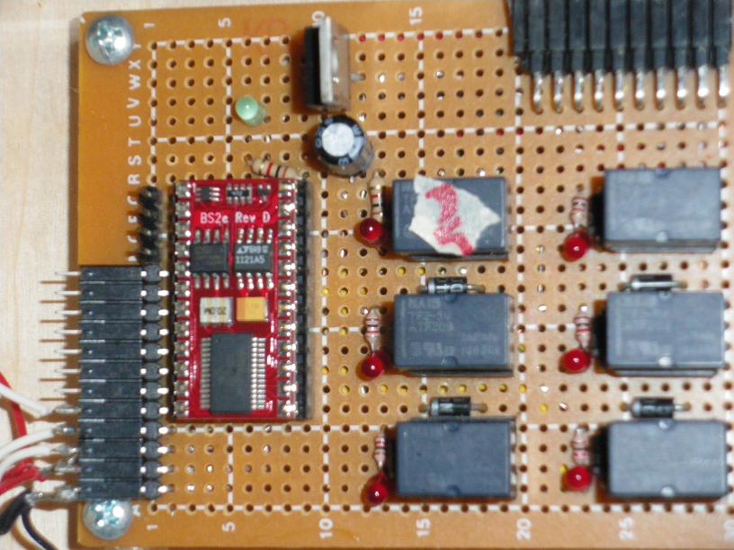
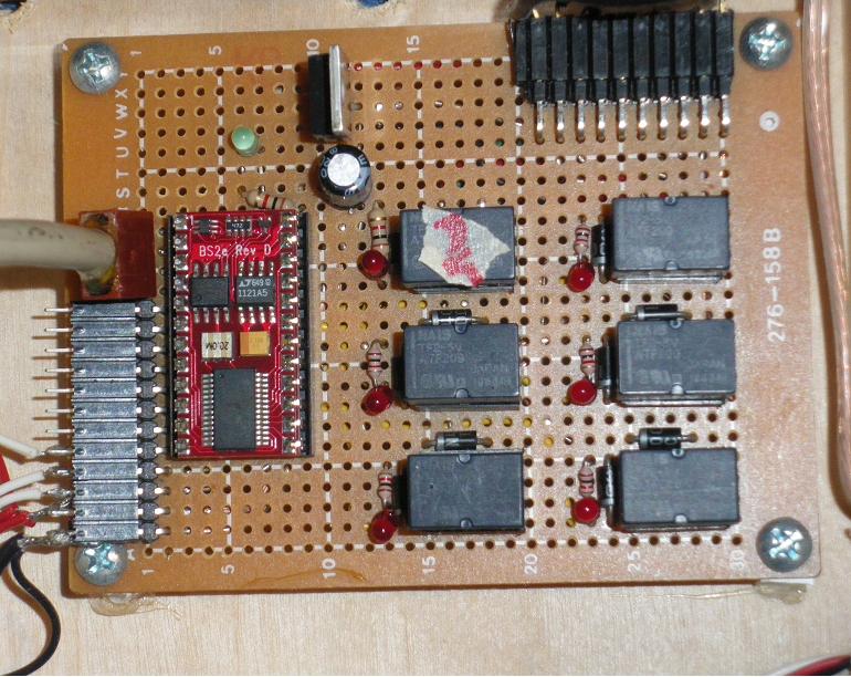
At the risk of stating the obvious, I want to share my thoughts & methods about building your own PC board & cable for a handwired Stamp project. I have seen several posts asking about this. Using premade boards with a 9-pin serial cable connector works fine, but it's quite easy to "roll your own" board to save dollars and board space. The BS2 family is much less finnicky and more stable than some other microcontrollers which require lots of extra support components mounted on the board. I start with an empty PC board (I use a "Shack" board, such as 276-158), solder a 24 pin socket to it. Then I add a 4-pin male header to pins 1-4; a 7805 regulator and 100 uF filter cap to pin 21 (Vdd, +5) and pin 23 (Vss, ground) and I'm done except for my I/O connections.
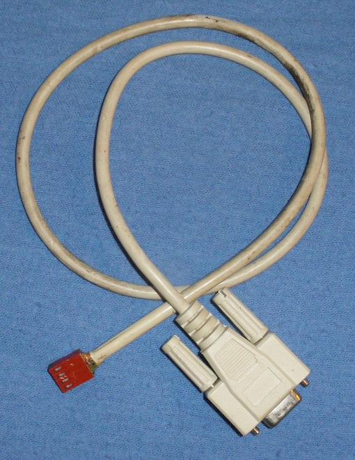
I cut a serial cable and attached a 4-pin female header to it, and seperately connected cable wires to DB9 pins 6 & 7 for auto port detection. A very compact connection taking minimum real estate on the board.
Stamp pin 1 to DB9 pin 2
Stamp pin 2 to DB9 pin 3
Stamp pin 3 to DB9 pin 4
Stamp pin 4 to DB9 pin 5
Not rocket science, but useful file info.
Comments
Thanks,
DJ
I noticed that i too made a whole set of little adapter cables for circuit boards
and breadboards over the years, but i
thought that the reset line should have the couple of pulsforming capacitor.
But i don't see anything on the cable or the circuit board.
I have here a photo with some adapters that include capacitors:
http://apsdev.com/stamp/cap.jpg
http://apsdev.com/stamp/dscf485b.jpg
The female adapter is very usefull as you only need to have
4 header pins on a board to program a basic or javelin stamp:
http://apsdev.com/p2podmockup/dscf0008s.jpg
Hello!
Exactly what specie of BS2 devices is that fellow? Is it the basic BS2 unit? Or the one who's next in line? You mention using a 24Pin DIP socket, and, ah, that's the first one up.
For me personally I would use a 24Pin DIP socket WW* :smilewinkgrin:one instead, and follow the rest of your guides. Of course since I already have an external power supply who can deliver straight 5v at the predictables typically used by an ordinary computer, the PS end can be deleted. As for the serial stuff, I already have a few already attached to connectors, in this case they are along the lines of the ones used by the older computers to attach to their serial ports.
Oh and for the I/O mount, I'd add a 16Pin DIP socket WW* :smilewinkgrin:one and add the one I use also for my Stamp1 board.
As for boards, I have here most of the ones RS makes except the number you quoted.
----
WW* = Wire Wrapped. :smilewinkgrin:
And a cheerful congrats for you and your scope win today!
I made that cable for the 1995 Trinity Firefighting robot contest, so I've been using it for 15+ years now. Still going strong!
@Buck: Nice to hear someone still likes wirewrapping! I still like point to point soldering. Keeps me honest.
@Tink: Thanks, I can use this 'scope!
Two capacitors shown in this diagram, but my cable does not have them. Might be for necessary for certain stamps; I have never had any problems with BS2, BS2E, and BS2SX.
Hello!
No they are not. They are the solder cup type, and pre-wired. They were originally used by the older PC community to bring the ports from the motherboard to the case.
I need to quickly and reliably connect wires from switches, etc... to my mother board.